


16
ENGLISH
EN
If the cables are interchanged, the gen-
erator and the battery will be damaged.
The engine must never be driven with
the battery disconnected. There is a risk
of serious damage to the generator and
the electrical system.
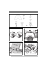
2.4 Seat switch
(Comfort, President, Excellent)
See fig. 6. At the underside of the seat is a switch,
which plays an important role in the machine’s
safety system located.
Assemble the switch as follows:
1. Loosen the switch from the cables.
2. Assemble the switch at the underside of the seat
with the screws (K).
3. Reconnect the cables to optional pins at the
switch.
2.5 Seat
See fig. 7. Install the mounting in the rear (upper)
holes as follows:
1. Install the shoulder washers (G) on the screws
(H).
2. Insert the screws through the slots in the brack-
et. Place a washer (J) between the seat and the
bracket.
3. Tighten the screws in the seat. Tightening
torque: 9±1.7 Nm.
If the screws are tightened more than
9±1.7 Nm, the seat will be damaged.
4. Check that the seat moves easily in the slots in
the bracket.
Install the mounting in the front (lower) holes as
follows:
1. Install a washer (J) on each knob (I).
2. Insert the knobs through the slots in the bracket
and tighten by hand in the seat.
3. Fold the seat down and place it in the desired
position.
4. Tighten the screw knobs (I) by hand.
The screw knobs (I) and the seat will be
damaged if tools are used.
The seat can be folded. If the machine is parked
outside when it is raining, fold the seat forward to
protect the seat cushion from getting wet.
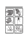
2.6 Arm rests (Pro20)
See fig. 8, 9. The arm rests and the installation
components are supplied in a separate box. Assem-
ble as follows:
1. Assemble the left and right mounts onto the
seat. Use 3 screws (Q) supplied at each side.
2. Assemble the arm rests with screws (R), nuts
(S) and spacers (T).
3. Tighten the screws so that the arm rests simply
can be folded up/down.
2.7 Steering wheel
See fig. 10. In order to minimise the axial play in
the steering column, the shim washers (E) and/or
(F) must be installed on the steering column be-
tween the steering column jacket and the bracket
as follows.
1. Install the steering column jacket on the steer-
ing column and secure by knocking in the ten-
sion pin (D) approximately 1/3 of its length.
2. Pull the steering column jacket and the steering
column up.
3. From the outside, check whether no washers,
the 0.5 mm washer, the 1.0 mm washer or both
washers can be inserted into the gap. The wash-
er/washers must not be forced in, as there must
be a little axial play.
4. Pull out the cotter pin and dismantle the steering
wheel jacket.
5. Install the washer/washers in accordance with
point 3 above.
6. Install the steering column jacket on the steer-
ing column and secure by knocking in the ten-
sion pin fully. Use a counterhold.
2.8 Towing hitch
See fig. 11. Screw the towing hitch (A) into the two
holes on the underside of the rear axle using screws
(B+C). Tighten the screws properly.
Tightening torque: 22 Nm.
2.9 Tyre pressure
Check the air pressure in the tyres. Correct air
pressure:
Front: 0.6 bar (9 psi)
Rear: 0.4 bar (6 psi)
2.10Accessories
For the installation of accessories, see separate in-
stallation guide supplied with each accessory.
Note: The cutting deck is regarded as an accessory
here.