


42
ENGLISH
EN
5. Tighten the screw (V) until the gear lever remains in the
gear positions in the panel plate.
6. Set down the machine on its wheels.
3.7 CHECKING THE CONTROL WIRES
The control wires might need adjusting before using the
snow thrower for the first time.
See ADJUSTING THE CONTROL WIRES below.
3.8 TYRE PRESSURE
Check the air pressure in the tyres. See “6.5”.
4 CONTROLS
The motor is equipped with a protection grid. The
motor may never be started without the grid fitted
or with a defect grid.
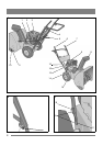
See fig. 1.
4.1 THROTTLE (16)
Controls the engine’s revs. The throttle has three positions:
1. Full throttle
2. Idling.
4.2 CHOKE (3)
Used when starting a cold engine. The choke has two
positions:
1. The choke is open
2. The choke is closed (for cold starting)
4.3 STOP SWITCH (13)
Used to stop the engine. The switch has two positions:
0– The engine stops, engine can not start.
1– The engine can be started, engine running.
4.4 STARTING HANDLE (12)
Manual cord start with rewinding.
4.5 DIPSTICK (15)
For filling and checking the oil level in the engine.
The dipstick has two level marks:
FULL = maximum oil level
ADD = minimum oil level
4.6 FILLER CAP (8)
For filling with petrol.
4.7 FUEL COCK(3)
The fuel cock opens the fuel supply to the carburettor. The
fuel cock shall always be closed when the machine is not in
use.
Downwards - open.
To the right - closed.
4.8 OIL DRAINING PLUG (14)
For draining the old engine oil when changing the oil.
4.9 SPARK PLUG PROTECTION (1)
The protection is easily removable by hand. The spark plug
is located under the protection.
4.10 GEAR LEVER (4)
The machine has 5 forward gears and 2 reverse to regulate
the speed.
The gear stick must not be moved if the driving clutch
lever is depressed.
4.11 CLUTCH LEVER- DRIVING (6)
Engages the wheels when put into gear and the lever
is pushed towards the handle.
Situated on the left side of the handle.
4.12 CLUTCH LEVER- AUGER (7)
Connects the auger and fan when the lever is pushed
down towards the handle.
Situated on the right side of the handle.
4.13 ADJUSTMENT LEVER (5)
Changes the direction of the discharged snow.
1. Turn the lever clockwise – the discharge turns to
the left.
2. Turn the lever anti-clockwise – the discharge turns
to the right.
4.14 SHOES (11)
Used to set the height of the auger housing above the ground.
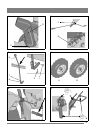
4.15 WHEEL LOCK
See fig. 7. The left wheel is mounted on the wheel shaft with
the help of a locking pin. The locking pin can be moved to
two positions:
A) Inner position – two-wheel drive.
B) Outer position – one-wheel drive. Simplifies
manoeuvring the machine when turning.
- Used during lighter conditions.
- When storing the machine.
4.16 CHUTE DEFLECTOR (9)
Losen the wing nuts and adjust the chute deflector to a
suitable height.
Low - shorter ejection distance.
High - longer ejection distance.