


5
ENGLISH
GB
GENERAL
This symbol means WARNING. Per-
sonal injury and/or damage to property
can occur if the instructions are not fol-
lowed carefully.
You must read these operating instruc-
tions and the enclosed pamphlet
“SAFETY INSTRUCTIONS” carefully
before starting the machine.
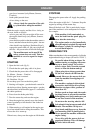
SYMBOLS
The following symbols are displayed on the ma-
chine to remind you of the care and attention re-
quired when using the machine.
The symbols mean:
Warning!
Read the instruction book and safety man-
ual before using the machine.
Warning!
Beware of objects being flung out. Keep
spectators away.
Warning!
Always use hearing protectors.
Warning!
This machine is not intended to be driven
on public roads.
Warning!
The machine, equipped with original ac-
cessories, must not be driven in any direc-
tion on slopes with a gradient of more than
10°.
Warning!
Risk for burn injuries. Do not touch the si-
lencer.
CONTROLS AND
INSTRUMENTS
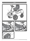
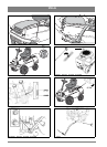
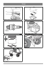
Items 1 - 9, see figures 1 - 3.
1. ACCESSORY LIFTER
Pedal for lifting front-mounted accessories to
transport position.
To lift up the accessory, press down the pedal as far
as it goes. Release the pedal and the accessory lift-
er will now be locked in the lift position.
To lower the accessory, press the pedal to release
the lock. Lower the accessory lifter to working po-
sition by slowly lifting your foot from the pedal.
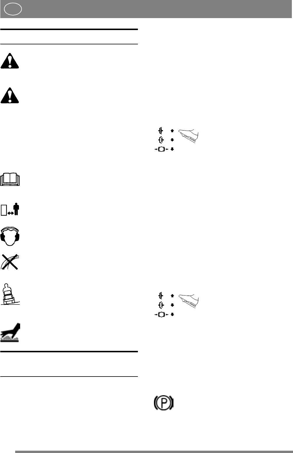
2A. SERVICE BRAKE/CLUTCH
(Master - Senator - Comfort)
Pedal which combines both the service brake and
clutch. Three positions:
1. Pedal released – forward drive
engaged. The machine starts to
move if a gear is engaged. The
service brake is not activated.
2. Pedal pressed halfway down –
front drive disengaged, it is not
possible to change gear. The
service brake is not activated.
3. Pedal pressed fully down –
front drive disengaged The serv-
ice brake is fully activated.
NOTE! Do not regulate the speed by slipping the
clutch. Use a suitable gear instead to obtain the
right speed.
2B. SERVICE BRAKE
(President - Royal)
Pedal which activates the machine’s brake system.
Three positions:
1. Pedal released – forward drive
not engaged.
2. Pedal pressed halfway – front
drive disengaged The service
brake is not activated.
3. Pedal pressed fully down –
front drive disengaged The serv-
ice brake is fully activated.
3. PARKING BRAKE
Inhibitor to lock the brake pedal in depressed posi-
tion.
Press down the brake pedal fully. Move
the inhibitor to the right and then release
the brake pedal.
The parking brake is released by pressing the brake
pedal. The spring-loaded inhibitor slides to one side.