48
ENGLISH
EN
The articulated steering means that the machine
can turn around trees and other obstacles with an
extremely small turning radius.
2.3 Safety system
The machine is equipped with an electrical safety
system. The safety system interrupts certain activ-
ities that can entail a danger of incorrect manoeu-
vres. For example, the engine cannot be started if
the clutch-parking brake pedal is depressed.
The operation of the safety system must
always be checked every time before
use.
2.4 Controls
2.4.1 Implement lifter, mechanical (1:A)
To switch between working position and transport
position:
1. Depress the pedal fully.
2. Release the pedal slowly.
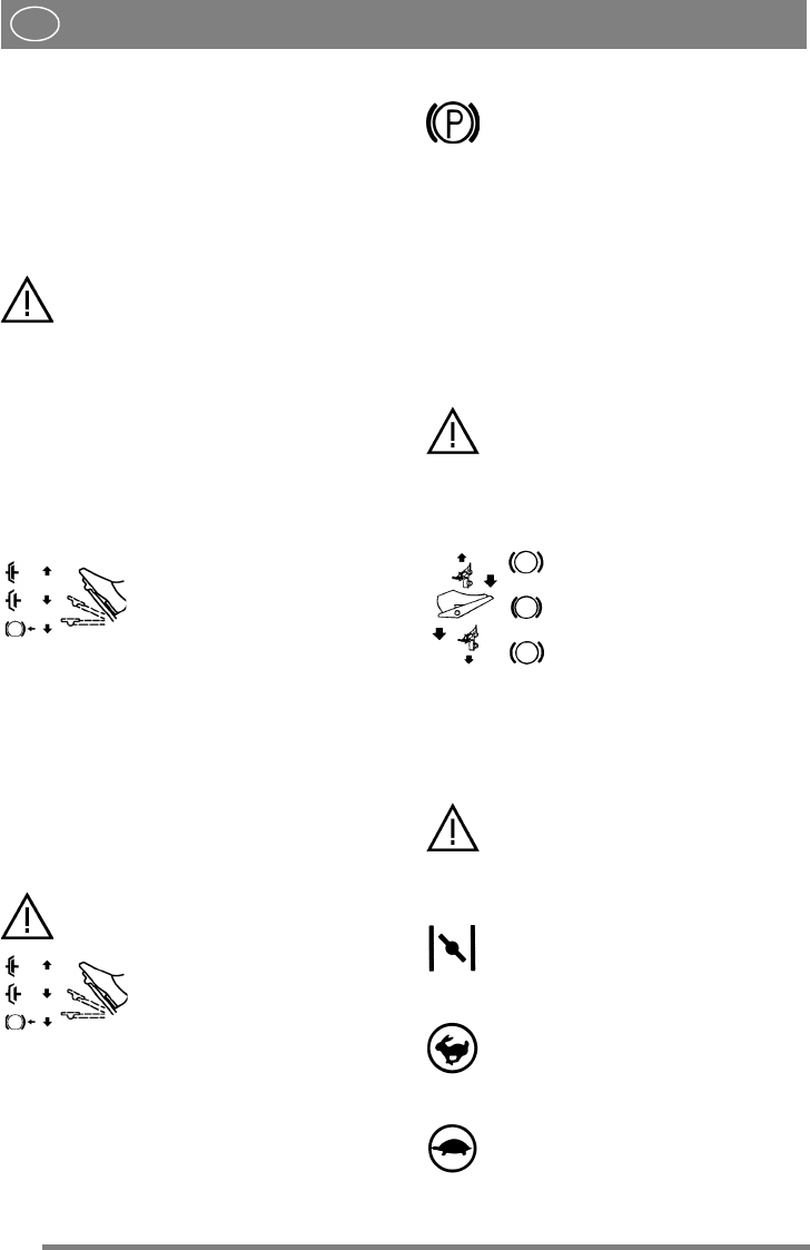
2.4.2 Service brake - Clutch (1:B) (Man)
A pedal that combines both service brake and
clutch. There are 3 positions:
1. Pedal released – forward drive
engaged. The machine will
move if a gear is engaged.
Service brake not activated.
2. Pedal depressed halfway –
forward drive disengaged, gear
shifting can be performed.
Service brake not activated.
3. Pedal fully depressed –
forward drive disengaged.
Service brake fully activated.
NOTE! You must never regulate the operating
speed by slipping the clutch. Use a suitable gear
instead, so that the right speed is obtained.
2.4.3 Clutch-parking brake (1:B)
(HST, 4WD)
Never press the pedal while driving.
There is a risk of overheating in the
power transmission.
The pedal has the following
three positions:
• Released. The clutch is not activated. The park-
ing brake is not activated.
• Depressed halfway. Forward drive disengaged.
The parking brake is not activated.
• Fully depressed. Forward drive disengaged.
The parking brake is fully activated but not
locked. This position is also used as emergency
brake.
2.4.4 Inhibitor, parking brake (1:C)
The inhibitor locks the “clutch-brake”
pedal in the depressed position. This func-
tion is used to lock the machine on slopes,
during transport, etc., when the engine is
not running.
Locking:
1. Depress the pedal (3:B) fully.
2. Move the inhibitor (3:C) to the right.
3. Release the pedal (3:B).
4. Release the inhibitor (3:C).
Unlocking:
Press and release the pedal (3:B).
2.4.5 Driving-service brake (1:F)
(HST, 4WD)
If the machine does not brake as expect-
ed when the pedal is released, the left
pedal (1:B) should be used as an emer-
gency brake.
The pedal determines the gearing ratio between the
engine and the drive wheels (= the speed). When
the pedal is released, the service brake is activated.
1. Press the pedal forward –
the machine moves forward.
2. No load on the pedal – the ma-
chine is stationary.
3. Press the pedal backward –
the machine reverses.
4. Reduce the pressure on the
pedal – the machine brakes.
2.4.6 Throttle and choke control (1:D)
(Prestige)
A control for setting the engine speed and to choke
the engine when starting from cold.
If the engine runs unevenly there is a
risk that the control is too far forward
so that the choke is activated. This dam-
ages the engine, increases fuel con-
sumption and is harmful to the
environment.
1. Choke – for starting a cold engine. The
choke position is located at the front of the
groove.
Do not operate in this position when the
engine is warm.
2. Full throttle – when the machine is in
operation, full throttle should always be
used.
The full throttle position is approximately
2 cm behind the choke position.
3. Idling.


