


37
ENGLISH
GB
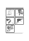
3.6 Cable for reverse control
Only applies to 500R-G.
The cable is marked R.
1. Hook the cable in the reverse control (1:C) and
insert the cable in the gap in the cable housing’s
mounting on the left handle.
2. Adjust the cable sleeve if necessary.
3.7 Drive cable
1. Hook the cable in the drive control (1:D) and in-
sert the cable in the gap in the cable housing’s
mounting on the left handle.
2. Adjust the cable sleeve if necessary.
3.8 Front protection
Install the front protection (5:J). Use the screws
supplied.
4 DESCRIPTION
The rotary cultivator is driven by a four-stroke en-
gine and is intended for soil cultivation in private
gardens. The most important parts and controls of
the rotary cultivator are described below.
4.1 Reverse control (1:C)
Only applies to 500R-G.
The control is used to start the rotor for reverse
when the engine is running.
The reverse control and drive control (1:D) must
never be activated at the same time.
Control in idle mode (forward) – No drive.
Control moved backwards – The machine
reverses.
4.2 Drive control (1:D)
The control is used to start the rotor for forward
motion when the engine is running.
The reverse control (1:C) and drive control must
never be activated at the same time.
Control in idle mode (down) – No drive.
Control pulled in – Forward operation.
4.3 Throttle and stop (1:A)
The control determines the engine’s rpm and has
start and stop positions.
4.4 Handle (1:B)
The handle has two handgrips that are used to op-
erate the machine over the area to be cultivated.
4.5 Fuel cap
See the accompanying engine manual.
Unscrew the fuel cap to fill with petrol. The fuel
cap must always be closed during operation.
4.6 Angle adjustment handle (1:E)
Release the knob and set the handle to the desired
angle.
Then retighten the knob again.
4.7 Height adjustment handle (1:F)
Slacken off the screws and set the handle to the de-
sired height.
Then retighten the screws again.
4.8 Oil filling/draining
Always check the oil level before start-
ing the engine.
See the accompanying engine manual.
Plug for oil filler and checking the oil level.
To drain the oil, the machine must be tilted so that
the oil runs out from the same hole.
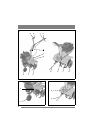
4.9 Auxiliary wheel (1:H)
The auxiliary wheel is intended to assist transport
of the machine and has two positions.
• The auxiliary wheel must not be installed when
carrying out work.
• The auxiliary wheel must be installed when
transporting.
Remove/install the auxiliary wheel as follows:
1. Pull out the locking pin (2:A).
2. Remove the auxiliary wheel downwards.
3. Reinstall the locking pin in the auxiliary wheel
arm.
Install in reverse order
4.10Rotors (1:J)
Nobody must be close to the dangerous
rotors during operation.
The rotors are made of special steel and work
the soil at the same time as the machine is pro-
pelled forwards.