


6
ENGLISH
GB
SYMBOLS
The following symbols appear on the machine.
They are there to remind you of the care and
attentionrequiredinuse.
This is what the symbols mean:
Warning! Read the Instruction Book and
Safety Manual before using the machine.
Warning! Keep onlookers away. Beware
of objects being flung out.
Warning! Keep hands and feet clear of the
cutting deck when the machine is running.
Warning! Before starting any repair work,
remove the spark plug cable from the
spark plug.
IMPORTANT
Equipment which is marked with an asterisk (*)
comes as standard in certain models or countries.
Certain models do not have throttle control. The
engine’s speed is set for optimal function and
minimal exhaust emissions.
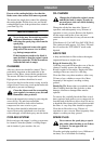
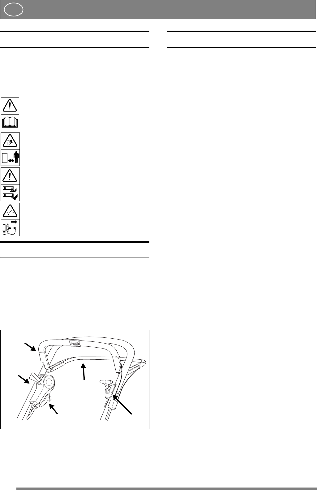
INTRODUCTION
1. Throttle control (*)
2. Clutch loop
3. Start/Stop loop
4. Electric start (*)
5. Variator control
ASSEMBLY
LOOSE PARTS IN THE BOX
1 ignition key (*)
1 battery charger (*)
1 socket wrench
2nutcaps
+ Instruction books
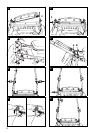
FLAP
Install the flap according to fig. 1-2.
1. Insert the shaft into the hole on the right-hand
side.
2. Fold down the flap so that the left-hand end of
the shaft is directly opposite the hole.
3. Insert the left-hand end of the shaft into the hole
by pressing shaft’s the right-hand end. Make
sure that the shaft is centred.
HANDLE
1. Remove rear screw, nut and washer and fold up
the lower part of the handle (fig. 3).
2. Screw the lower part of the handle without
tightening (both sides). Ensure that the lug for
the starter cord is correctly positioned (fig. 4).
3. Install the upper part of the handle using
screws, washers and locking wheels (fig. 5).
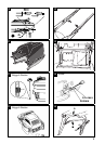
4. Adjust the handle so that the handlebar is
horizontal.
5. Set the required height for the handle and tighten
the screws A and B properly (fig. 4).
6. Thread the nut caps onto the front screw heads
B (fig. 6).
7. Fold down the spring struts so that the flap is
secured (fig. 7).
8. Carefully pull the starter handle and thread the
starter cord through the lower and upper lugs.
Tighten the upper lug (fig. 8).
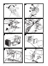
ENGINE BRAKE CABLE
Secure the engine brake cable to the engine brake
(fig. 9). Note that the cable should be installed in
the direction of the handle.
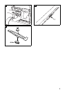
CABLE HOLDERS
Secure the cables in the cable holders (fig. 10):
4
3
2
5
1