9
30SS, 36SS, 45SS
Rev: 12/21/2011
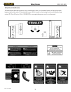
Assembly Instructions
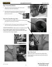
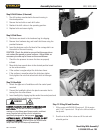
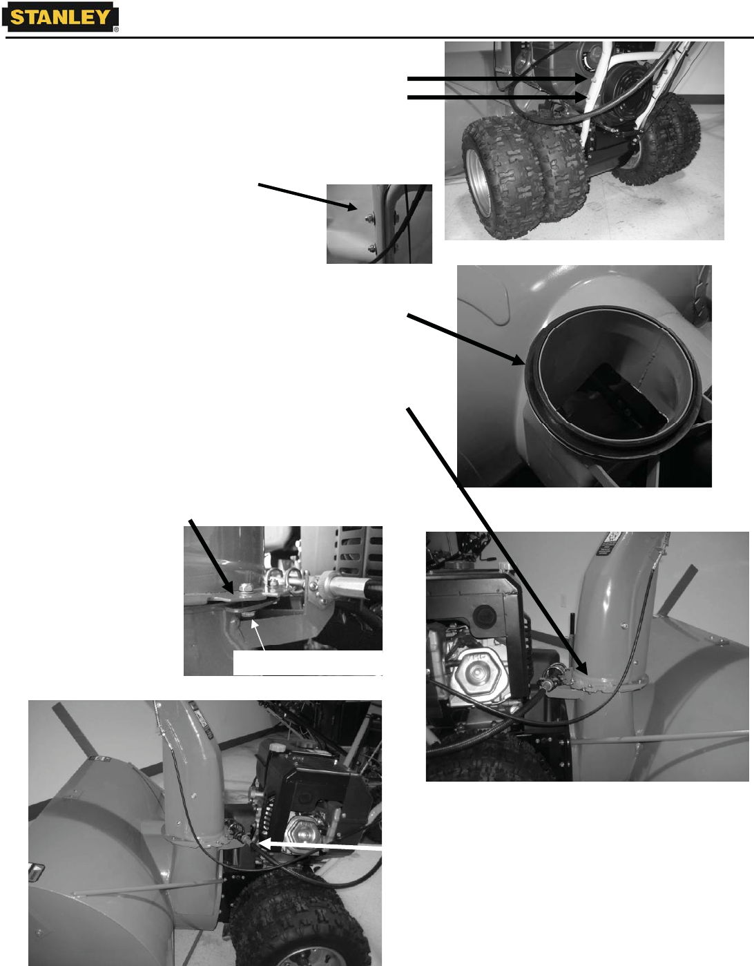
Step 1: Control Panel Handles
1. Align the two holes on each side of the control panel
handles over the lower handle frame.
2. Insert the bolts through the handlebar holes and frame
holes. Secure in place with hardware provided. Insert
bolts from the inside.
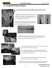
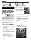
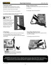
Step 2: Directional Discharge Chute
1. Fit round spacer onto impeller housing before installing chute.
Apply light coat of grease onto spacer.
2. Install the bolts for the retainer brackets bottom-up as shown.
Insert the plastic spacer between the two metal parts.
DO NOT OVERTIGHTEN. If the bracket is too tight the chute
will not move properly. Ensure there is enough space
between the impeller housing and the bracket on all sides
so that the chute rotates smoothly.
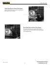
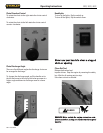
Step 3: Chute Crank
Attach the cable coming from the middle of the
control panel by screwing the cable end onto the
crank section.
Bolt installed bottom-up
Need Help With Assembly?
1-919-550-3221 ext. 158


