


Simplicity / Snapper ZTR
TP 300-7337-01-CH-SMN
8/20074
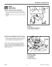
Uncrating
1. Using a reciprocating utility saw or equivalent, cut
crate away from bottom skid. Remove crate. Remove
shrink-wrap plastic.
2. Cut any banding securing the unit.
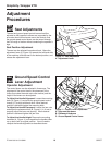
3. Release parking brake.
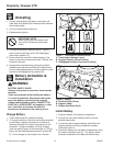
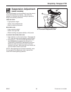
4. Pull both transmission release levers (A, Figure 1)
back and out so that they lock in the disengaged
(free-wheel) position (C).
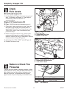
5. Be sure there are no nails or sharp objects on the
bottom of the skid to puncture the tires. Roll the rider
forward off the skid.
6. Engage the transmissions by pulling the hydraulic
release levers rearward and inward to release them
from the disengaged position and allow them to move
forward to the engaged (drive) position (B).
IMPORTANT NOTE
When cutting crate from bottom skid,
use caution around tires and mower
rollers.
Battery Activation &
Installation
Charge Battery
1. Tip the seat forward to access the battery.
2. To charge the battery, follow the instructions provided
by the battery charger manufacturer as well as all
warnings included in the safety rules section of this
document. Charge the battery until fully charged
(until the specific gravity of the electrolyte is 1.250 or
higher and the electrolyte temperature is at least 60°
F). Do not charge at a rate higher than 10 amps.
WARNING
BATTERY SAFETY RULES
• Battery acid causes severe burns. Avoid contact
with skin.
• Wear eye protection while handling the battery.
• To avoid an explosion, keep flames and sparks
away from battery, especially while charging.
• When installing battery cables, CONNECT THE
POSITIVE (+) CABLE FIRST and negative (-) cable
last. If not done in this order, the positive
terminal can be shorted to the frame by a tool.
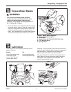
Install Battery
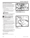
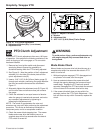
1. Install the battery in the battery compartment
2. Connect the red positive battery cable (A) to the
positive battery post.
3. Connect the black negative battery cable (B) to the
negative battery post using a capscrew, washer,
lockwasher and nut.
4. Secure the battery into the battery compartment using
the rubber hold down strap (C). The battery cables
should be underneath the rubber hold-down strap.
Figure 2. Battery
A. Positive Cable & Cover
B. Negative Cable
C. Rubber Hold-Down Strap
Figure 1. Transmission Release Levers
A. Transmission Release Levers
B. Engaged Position (Drive Position)
C. Disengaged Position (Free-wheel Position)
A
B
C
B
A
C