


22
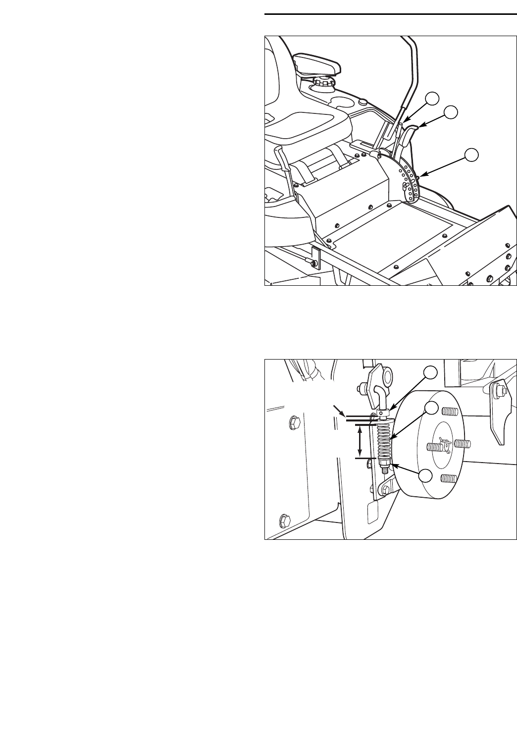
2"
(5 cm)
3/16"
(5 mm)
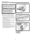
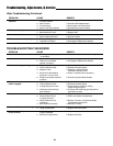
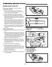
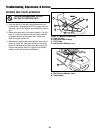
Figure 24. Parking Brake Adjustment
A. Brake Spring
B. Set Collar
C. Locknut
PARKING BRAKE ADJUSTMENT
Brake Adjustment
1. Disengage the PTO, stop the engine, block the front
wheels, remove the ignition key, and engage the
parking brake.
2. Elevate the rear end of the unit and remove the rear
wheels.
3. Check the brake spring (A, Figure 24) length (both
wheels). With the brake engaged the compressed
spring length should be 2” (5 cm). If not, adjust the
locknut (C, Figure 24) to achieve the compressed
spring length of 2” (5 cm).
4. After achieving the correct spring compression, check
the set collar gap (B, Figure 24). With the parking
brake engaged, the set collar gap should be 3/16"
(5 mm). If not, loosen the set collar screw and move
the collar to the correct position.
NEUTRAL ADJUSTMENT
If the unit creeps forward or backward with the control
levers in their neutral positions, see your dealer.
A
C
B
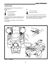
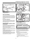
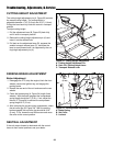
Figure 23. Cutting Height Adjustment
A. Cutting Height Adjustment Pin
B. Deck Lift / Cutting Height Lever
C. Transport Release Lever
B
C
A
CUTTING HEIGHT ADJUSTMENT
The cutting height adjustment pin (A, Figure 23) controls
the mower cutting height. The cutting height is
adjustable between 1-1/2” (3,8 cm) and 4-1/2” (11,4cm).
Pulling the lever back fully locks the control in transport
position.
To adjust cutting height:
1. Pull the adjustment lever (B, Figure 23) back fully
until it locks in transport position.
2. Remove the cutting height adjustment pin (A) and
insert it into the desired hole.
3. Pull back on the adjustment lever (B), squeeze the
smaller transport release lever (C), and allow the
lever to move forward until it is supported by the cut-
ting height adjustment pin (A).
Troubleshooting, Adjustments, & Service