


19
CHECK RIDER SAFETY
SYSTEM
Service Interval: Every 100 hours, every spring/fall,
and after storage of 30 days or longer.
This unit is equipped with safety interlock switches.
These safety systems are present for your safety. Do
not attempt to bypass safety switches, and never tamp-
er with safety devices. Check their operation regularly.
Operational SAFETY Checks
Your unit is equipped with a seat switch safety system. Check
the seat switch operation every fall and spring with the follow-
ing tests.
Test 1 — Engine should NOT crank if:
• PTO switch is ON, OR
• Brake pedal is NOT fully depressed (parking brake
OFF), OR
• The cruise control lever is NOT in NEUTRAL.
Test 2 — Engine SHOULD crank and start if:
• Operator is sitting in seat, AND.
• PTO switch is OFF, AND
• Brake pedal is fully depressed (parking brake ON),
AND
• The cruise control lever is in NEUTRAL
Test 3 — Engine should SHUT OFF if:
• Operator rises off seat.
Test 4 — Blade Brake Check
The mower blades and mower drive belt should come
to a complete stop within five seconds after the PTO
switch is turned OFF. If mower drive belt does not stop
within five seconds, contact an authorized dealer.
NOTE: Once the engine has stopped, the PTO switch
must be turned OFF and the ground speed control
levers must be locked in their PARK positions in order
to start the engine.
WARNING
If the unit does not pass a safety test, do not
operate it. See an authorized Dealer. Under
no circumstance should you attempt to defeat
the purpose of the safety interlock system.
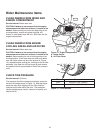
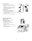
CLEANING THE BATTERY AND
CABLES
Service Interval: 100 Hours
1. Disconnect the cables from the battery, negative
cable first (B, Figure 21).
2. Remove the rubber strap securing the battery, and
remove the battery.
3. Clean the battery and battery compartment with a
solution of baking soda and water.
4. Clean the battery terminals and cable ends with a
wire brush until shiny.
5. Reinstall the battery and secure with the rubber strap.
6. Reattach the battery cables: first attach the positive
cable (see A, Figure 21), then attach the negative
cable (B).
7. Coat the cable ends and battery terminals with petro-
leum jelly or non-conducting grease.
WARNING
Be careful when handling the battery. Avoid
spilling electrolyte. Keep flames and sparks away
from the battery.
When removing or installing battery cables,
disconnect the negative cable FIRST and reconnect
it LAST. If not done in this order, the positive
terminal can be shorted to the frame by a tool.
Always wear safety glasses and gloves when
handling batteries.
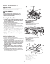
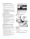
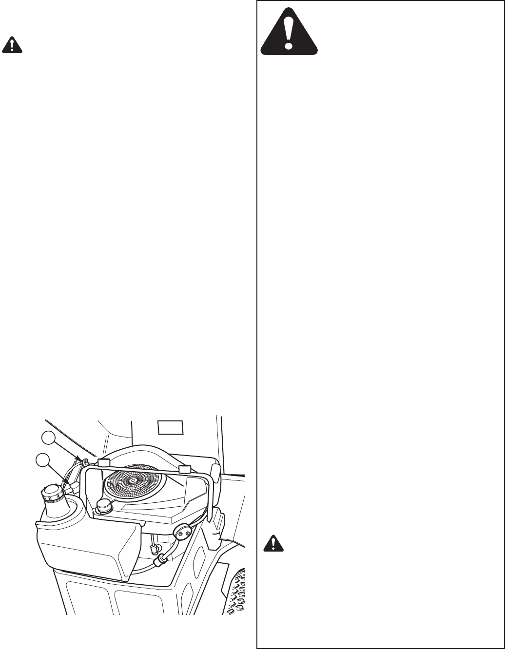
Figure 21. Engine Compartment
A. Positive (+) Battery Cable
B. Negative (-) Battery Cable
A
B