


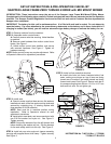


STEP 10: MOWER DECK ADJUSTMENT (LEVELNESS)
SIDE to SIDE and FRONT to REAR
Before making deck leveling adjustments, inflate rear tires to
12 PSI and front tires to 25 PSI. When adjusted correctly,
the deck will be level side to side within 1/8”, have a low cut
setting of approximately 1” (1-1/4” for 61 deck), and the
blades pitched approximately 3/16” higher at the rear. If
adjustment is needed:
A. Place machine on a smooth level surface.
B. Check blade tips by rotating blades until tips are pointing
to the sides of the deck. Check the measurement of outside
blade tips to the ground on both blades. The measurement
of each of the outside blade tips should be within 1/8” of
each other. If measurement of the blade tips is not within
1/8”, adjustment should be made to the correct measure-
ment.
C. Move deck lift lever and set the mower deck to the
highest cutting position.
D. Relieve tension on deck lift assist spring by loosening nut
on eyebolt.
E. Place 1” blocks (1-1/4” for 61 deck) under the front and
rear edge of the mower deck.
F. Set the mower deck to the lowest cutting position until
deck rests on the blocks.
G. Loosen the top nuts that secure both front deck support
eyebolts. Adjust bottom nuts until eyebolts are tight, then
retighten top nuts.
H. Loosen the bottom nuts that secure both rear deck
support eyebolts. Adjust top nuts until eyebolts are tight,
then tighten bottom nuts securely.
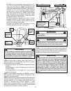
I. Set the mower deck to the transport position and recheck
side to side blade tip dimensions. The difference between
the two should be 1/8” or less.
NOTE: The deck timing rod (rod that runs from front deck lift
arm to rear deck lift arm) is preset at the factory and requires
no adjustments.
J. The leveling blocks used in Step E should result in a prop-
er deck pitch. If a pitch adjustment is required, use the two
rear deck support eyebolts. Adjust up or down as required.
K. Reinstall deck lift assist spring. Place deck in transport
position. Tighten nut on eyebolt until 2-3/4” of threads pro-
trude past end of nut.
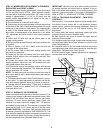
STEP 11: HYDRAULIC OIL RESERVOIR
Check the level of the fluid in both of the fluid reservoirs. The
reservoirs are located underneath the operator’s seat. Wipe
away all dirt and debris from around reservoir cap before
removing. Oil must remain absolutely clean! Check with
machine on a level surface with engine “OFF”. Fill reservoir
as needed to bring level up. The reservoir is properly filled
when the fluid level is 1½” below the top of the filler neck.
DO NOT OVER FILL. Use clean, fresh premium automotive
oil having a viscosity equivalent to SAE 20W50 API SL. The
fluid should be chemically stable, incorporating rust and oxi-
dation inhibitors. Make sure funnels, pouring spouts and oil
can are completely clean. Reinstall reservoir cap.
IMPORTANT: Re-check fluid level after operating machine
for several minutes and adjust level as needed. If one or
both of the wheel drive systems is not pulling properly, the
hydraulic system may need to be purged of entrapped air.
Refer to STEP 13, “HYDRAULIC SYSTEM, PURGING”.
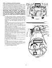
STEP 12: TRACKING ADJUSTMENT – TWIN STICK
CONTROLS
Start machine. If the machine does not track straight when
the Motion Control Levers are in the maximum forward
speed position, perform the following adjustment. Rear tire
pressure must be set to 12 PSI before making this
adjustment.
A. Loosen bolts that secure adjustment plates and slide
plates all the way forward. Retighten bolts.
B. Start machine and drive in smooth flat open area at
maximum forward speed.
C. If machine tracks to the right, loosen bolts that secure the
left adjustment plate. Move plate rearward to slow the left
wheel. Retighten bolts.
D. If machine tracks to the left, loosen bolts that secure the
right adjustment plate. Move plate rearward to slow the right
wheel down. Retighten bolts. See Figure 6.
E. Drive machine again. Repeat adjustment as necessary
until machine tracks straight.
3
FIGURE 6
LOOSEN BOLTS,
SLIDE PLATE TO
MAKE MACHINE
TRACK STRAIGHT
RIGHT SIDE MOTION
CONTROL LEVER
ADJUSTMENT
PLATE