


Section 4 - ADJUSTMENT & REPAIR
IL WARNING 41
DO NOT OVERFILL! Never attempt to service or I
charge the battery while it is installed on the machine.
DO NOT use "BOOST" chargers on the battery.
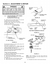
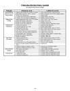
4.5.5. BATTERY TESTING
There are two types of battery tests: Unloaded and
Loaded. The unloaded test is the procedure that wilI
be discussed. It's the simplest and most commonly
used. An unloaded test is made on a battery without
discharging current. To perform unloaded testing,
check charge condition using either a hydrometer or
voltmeter.
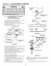
1. Using a voltmeter, voltage readings appear
instantly to show the state of charge. Remember to
hook the positive lead to the battery's positive
terminal, and the negative Iead to the negative
terminal.
2, A hydrometer measures the specific gravity of
each ceil. The specific gravity tells the degree of
charge; generally, a specific gravity of about 1.265 to
1.280 indicates fulI charge. A reading of 1.230 to
1.260 indicates the battery should be charged. The
Battery Condition chart below shows the charge level
as measured by syringe float hydrometer, digital
voltmeter and five ball hydrometer.
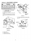
4,5.6. NEW BATTERY PREPARATION
1. Remove battery from carton.
2. Place battery in a well ventilated area on a level non-
concrete surface.
3. Remove battery cell caps. FilI cells as required
with electrolyte (purchased separately) to proper level.
Fill to 3/16" above cell plates. Filling battery with
electrolyte wilI bring the battery to 80% charged state.
4. With cell caps removed, connect battery charger to
battery terminals; RED to positive (+) and BLACK to
negative (-) terminal.
IMPORTANT: 3/16" above cell plates is the recommended
level. DO NOT place anything in battery other than specified
electrolyte.
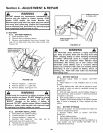
5. Slow charge the battery at 1 amp for 2 hours to
bring the battery to full charge.
6. After charging, check level of electrolyte and add
as needed to bring level to 3/16" above ceil plates.
7. Reinstall cell caps.
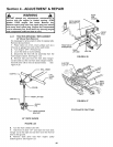
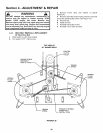
8. Slide battery partially into battery housing.
9. Connect positive (+) cable (red) first, from wiring
harness to the positive terminal (+) on battery using bolt
and nut provided in hardware bag. Connect negative (-)
cable (black) last, to negative terminal (-) on battery
using bolt and nut. Apply a small amount of grease over
terminals to prevent corrosion.
10. Insert battery completely into battery housing.
11. Reinstall seat assembly.
WARNING
Shield the positive terminal with terminal cover
located on battery harness. This prevents metal from
touching the positive terminal, which could cause
sparks. Cables must be connected to battery
terminals in the proper position. RED (Positive) cable
must go to the ( + ) terminal, BLACK (Negative) cable
must go to the ( - ) terminal.
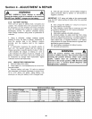
Battery Condition Chart
State of Charge
100% Charged w/Sulfate Stop
100% Charged
75% Charged
50% Charged
25% Charged
0% Charged
Syringe Hydrometer
1.280
1.265
1.210
1.160
1.120
Less than 1.100
Digital Voltmeter
12.80v
12.60v
12.40v
12.10v
11.90v
Less than 11.80v
Five Ball Hydrometer
Five Balls Floating
Four Balls Floating
Three Balls Floating
Two Balls Floating
One Ball Floating
Zero Balls Floating
30