18
Section 4 - ADJUSTMENTS & REPAIR
WARNING
DO NOT attempt any adjustments, maintenance,
service or repairs with the engine running. Stop
engine. Stop blade. Engage parking brake. Remove
key. Remove spark plug wire from spark plug and
secure away from plug. Engine and components are
HOT. Avoid serious burns, allow all parts to cool
before working on machine. Fuel Filler Cap and Vent
must be closed securely to prevent fuel spillage.
4.1 ENGINE ADJUSTMENTS & REPAIR
Refer to the engine owner’s manual for those
adjustments and/or repairs that can be made by the
owner.
4.2 MOWER DECK & COMPONENT ADJUSTMENTS
The following mower deck and component
adjustments and repairs can be made by the owner.
However, if there is difficulty in achieving these
adjustments and repairs, it is recommended that
these repairs be made by an authorized SNAPPER
dealer.
WARNING
Once blade is disengaged it should come to a stop in 3
seconds or less. If the blade continues to rotate after 3
seconds the blade brake must be adjusted. DO NOT
continue to operate the machine if the blade brake is
not operating properly.
4.2.1. MOWER DRIVE BELT ADJUSTMENT
(FOR 28" & 30" MODELS)
1. Remove mower drive belt cover. Refer to
Section “CHECK BLADE DRIVE BELT”.
2. Move blade lever up and over to the “ON”
position.
3. Place deck cutting height in the 3rd position.
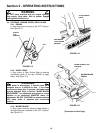
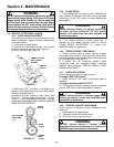
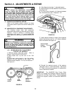
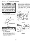
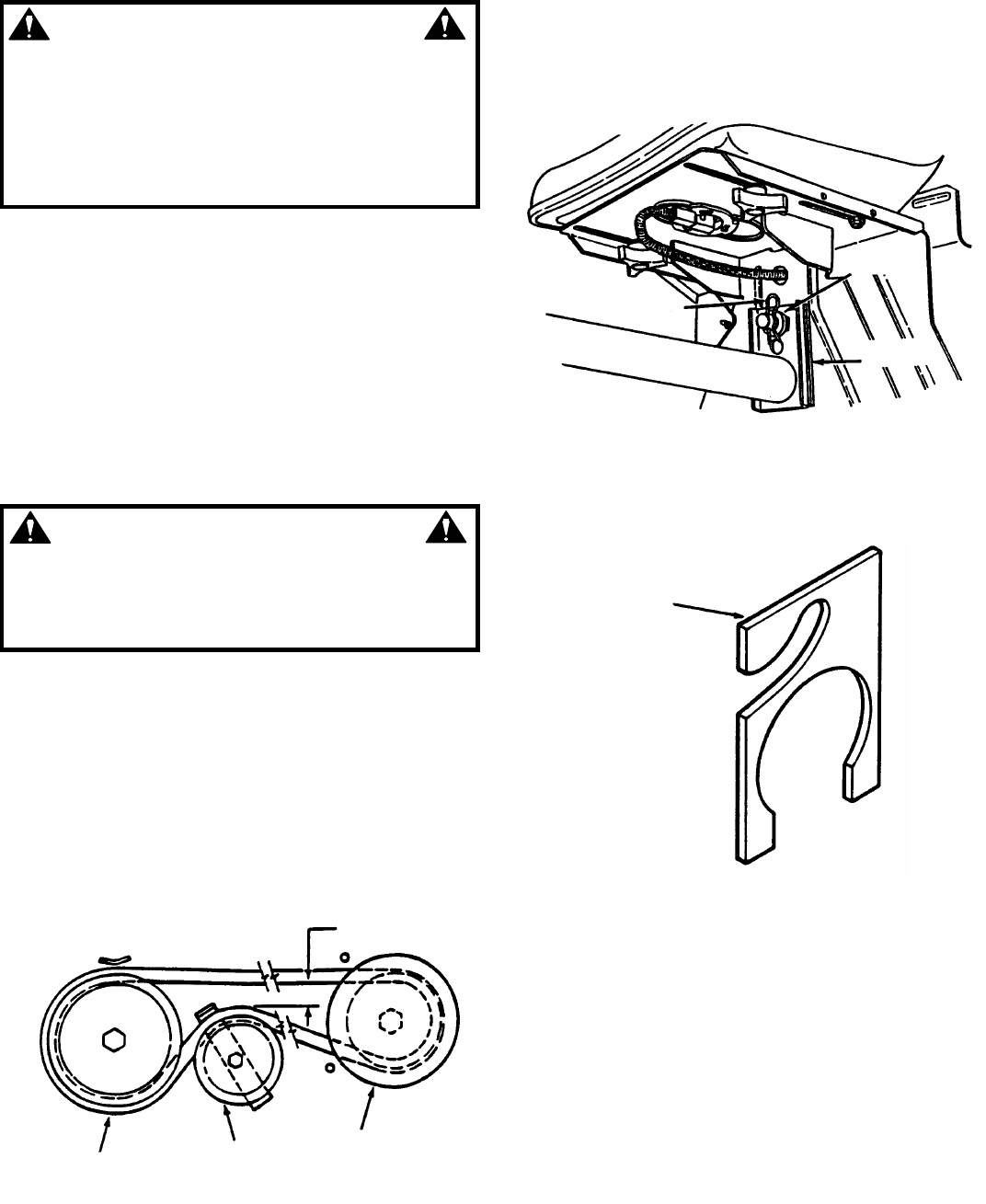
Measure the belt spacing at idler pulley. The
distance should measure 1-1/4” but no less than 1”.
See Figure 4.1.
FIGURE 4.1
4. If the distance is less than 1”, adjust belt tension.
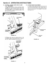
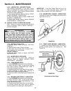
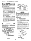
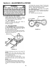
5. Remove hairpin and flat washers from pivot stud.
See Figure 4.2.
6. Pull front frame forward until distance between
belt, with blade lever “ON”, measures 1-1/4”.
FIGURE 4.2
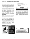
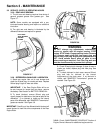
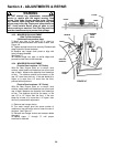
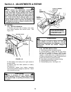
7. Install required number of snap-in frame spacers
behind channel pivot until the 1-1/4” distance between
belt is maintained. See Figure 4.3.
FIGURE 4.3
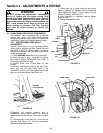
8. Reinstall the required amount of flat washers
removed in step “5.” and install hairpin. See Figure
4.2. Retain any remaining spacers for readjustment
when a new belt is installed.
IMPORTANT: The SNAPPER Rear Engine Rider
Models are shipped with additional spacers specifically
designed for the Rear Engine Rider. Should additional
spacers be required, contact an authorized SNAPPER
dealer.
1-1/4”
SPINDLE
PULLEY
IDLER
PULLEY
ENGINE DRIVE
PULLEY
ASSEMBLY
HAIRPIN
FLAT
WASHERS
FRAME
SPACERS
SNAP-IN FRAME
SPACER
P.N. 2-8395


