


SECTION 5 - MOWER ATTACHMENT SERVICE
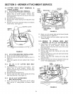
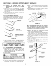
5.1.5. SPINDLE TO SPINDLE DECK BELT
INSTALLATION - 48", 52", & 61" CU'I-rlNG
DECKS
1. Route new belt for 48" cutting deck, 52" cutting
deck, and 61" cutting decks, onto bottom ,qroove of
center Spindle Pulley and Ieft hand Spindle Pulley.
See Figure 5.3.
2. Install cutting deck belt according to CUTTING
DECK BELT INSTALLATION.
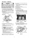
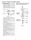
5.2 CUTTING BLADE SERVICE
Check Blades at frequent intervals to insure they are
securely tightened and in good condition. Replace if
chipped, bent, or notched. See Figure 5.4 for Blade
wear limits.
l NEW BLADE
,_....._ WEAR LIMIT
{NOTCH STARTS)
DANGEROUS CONDITION!
DO NOT USE ON MOWER!
_REPLACEWITH NEW
BLADE.
FIGURE 5.4
1. Use the following chart for ordering replacement
Blades for the 36", 48", 52" and 61" cutting decks.
I STANDARD BLADE REPLACEMENT
36" DECK 48" DECK 52" DECK 61" DECK
7029246 7029247 7029246 7029251
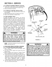
5.2.1. BLADE REMOVAL AND SHARPENING
1. Move the Mower to a smooth, level surface, turn the
Ignition Key to STOP position, remove Key,
disconnect Spark Plug Wire from Spark Plug and
secure Wire away from Plug.
2. Remove Blades.
WARNING
Take NOTE of the number of Blade Spacers that I
are under the Blade Mounting Nuts and on the_
Spindle side of the Blade. |
3. Clean and inspect each Blade for excessive wear
and damage. See Figure 5.4 for Blade wear limits.
4. Refer to the STANDARD BLADE REPLACEMENT
chart above for correct SNAPPER replacement
Blades.
5. Should Blades be in acceptable condition, sharpen
at 22 to 28 degrees. See Figure 5.5.
BLADE
HEAVY END
22° to 28°
OF BLADE
ORIGINAL CUTTING EDGE
1I64'
FIGURE 5.5
NOTE: When sharpening Blades, leave 1/64" untouched.
Razor sharp Blades will chip easily and dull quickly.
Commercial baIancers are available and should be used
in accordance with the manufactureCs instructions.
6. Balance each Blade after sharpening by grinding
metal from the heavy end of the blade.
7. Place the Blade mounting bolt into Blade and place
Blade spacers over bolt. Make certain each blade is
installed with the same amount of spacers removed.
8. Install Blade mounting bolt with spacers and blade
into spindle.
9. Install an equal amount of Blade spacers onto each
Blade mounting bolt.
10. Install the Blade mounting nut on each Blade
mounting bolt. See Figure 5.6.
11. Torque each Blade mounting bolt and nut to 70 - 80
foot-pounds.
.,..--.- AIR LIFT
ADJUSTING
SPACERS
MOUNTING
BOLT
BLADE
__BEVELED
WASHER
TIGHTEN TO70-80
FOOTPOUNDS
FIGURE 5.6
25