


16
SECTION 3 - OPERATING INSTRUCTIONS
3.7 HANDLE HEIGHT ADJUSTMENT
(Continued from previous page)
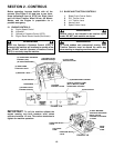
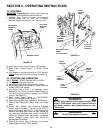
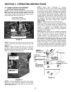
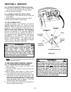
STEP 3: Insert rod (5/16” diameter x 20” long) through
alignment holes in the left and right traction control shift
lever arms and the tank support bracket. The rod
should pass through both the left and right traction
control shift lever arms. See Figure 3.9.
FIGURE 3.9
STEP 4: Disconnect the swivel from the right and left
traction control arms and loosen swivel jam nuts. See
Figure 3.8.
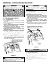
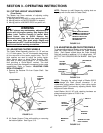
STEP 5: Loosen the upper bolt and nut on right and
left side of Mower which holds Handlebar to Support
Bracket. Remove the lower bolt and nut on each side.
Retain this hardware. See Figure 3.10.
FIGURE 3.10
STEP 6: Pivot the Handlebar up or down and reinsert
bolt and nut into desired hole position on each side.
Tighten both upper and lower bolts and nuts on each
side to 35 to 45 ft. lbs.
STEP 7: Adjust swivel (Clockwise or Counter-
Clockwise) until the pin on the swivel aligns perfectly
with the hole in the traction control arm. The traction
control lever must be held in the Neutral Latch position
when making this adjustment. Complete this adjustment
for both left and right swivels. Carefully reattach and
secure swivels to control arms. Tighten swivel jam nuts.
IMPORTANT: Both the left and the right swivels must
be installed in the same traction control arm speed
range setting. Mid range (middle hole) setting is
recommended.
STEP 8: Remove steel rod from shift lever arms.
STEP 9: Check to insure machine is securely blocked.
Start engine. Drive wheels should not rotate with both
Traction Levers latched in the Neutral position. If no
rotation is observed the handlebar adjustment
procedure is complete. If wheels do rotate proceed to
next step. STOP ENGINE.
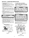
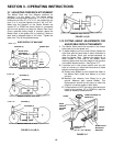
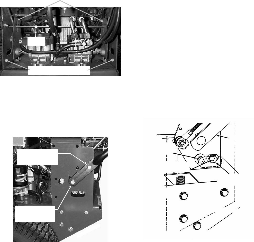
STEP 10: Wheel rotation will be stopped by adjusting
the eccentric on the pump arms on the right and left
pumps. Turning the eccentric slightly clockwise or
counter-clockwise will synchronize the pump and
traction controls for Neutral. See Figure 3.11. To turn
the eccentric, first loosen the bolt in the pump control
arm and the nut and bolt fastening the eccentric to the
pump control arm. With both Traction Levers latched in
Neutral, start engine. Turn eccentric slightly clockwise
or counter-clockwise until wheels stop rotating. Tighten
control arm bolts and eccentric nut and bolts. Check for
wheel rotation. Repeat eccentric adjustment if needed.
FIGURE 3.11
TRACTION
CONTROL SHIFT
LEVER ARM
LOOSEN BOLT
CONNECTED TO CONTROL
ARM
LOOSEN BOLT & NUT THAT
CONNECTS ECCENTRIC TO CONTROL
ARM
FUEL
TANK/HANDLEBAR
SUPPORT BRACKET
SHOWN IN PHANTOM
LEFT SIDE OF MACHINE SHOWN
ROTATE ECCENTRIC
CLOCKWISE OR COUNTER-
CLOCKWISE
HANDLEBAR
LOOSEN UPPER
BOLT & NUT
REMOVE LOWER
BOLT & NUT
LEFT & RIGHT TRACTION
CONTROL SHIFT LEVER ARMS
ROD
TANK SUPPORT BRACKETS