


3
unit assembly
Note: Please refer to Parts List for correct part identification and placement.
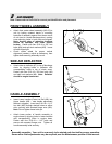
FRONT WHEEL ASSEMBLY
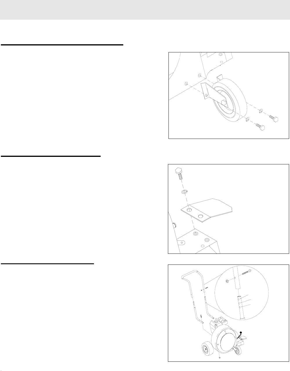
• Attach front caster wheel assembly (#19-23) to
unit by butting outward bends in mounting
brackets of assembly against front lower corner
of unit (next to blower discharge door), making
sure mounting holes in both parts are aligned.
Note: Angled edge of mounting brackets
should be upwards, with holes toward
bottom. Fasten with two 5/16-18 x 5/8” hex
bolts (#24) and split lock washers (#25). Leave
all bolts finger tight.
• Check caster wheel for proper vertical
alignment (camber), adjust as necessary, then
tighten bolts securing assembly to unit.
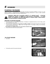
SIDE AIR DEFLECTOR
• Attach side air deflector (#7) to top of discharge
chute by aligning holes in deflector with
corresponding holes in top of chute snout.
Fasten with two 5/16-18 x 5/8 hex bolts (#8)
and split lock washers (#9). Note: Deflector
should be angled downward.
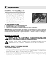
HANDLE ASSEMBLY
• Insert Lower handles (Parts List Ref. #28) into
Upper handle (#26 – note handle adjustment
feature in diagram). Insert one 5/16-18 x 1-1/2”
hex bolt (#29) through desired holes on either
side, securing with serrated flange nuts (#30).
Note: Do not tighten these bolts yet.
• Attach lower portion of handle assembly to
engine base by aligning holes in lower handles
with corresponding holes in engine base.
Fasten with four 5/16-18 x 1-1/2” bolts and
secure with serrated flange nuts. Tighten all
handle assembly bolts securely.
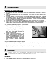
+1"
0
-1"
1
Assembly complete. Your unit is now ready to be started and checked for proper operation.
Some minor final adjustments may be required; see the Maintenance portion of this manual.