


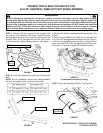
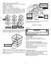
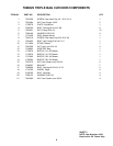


b. Install the catcher support onto the unit, securing with the
hardware noted in Figure 9. Tighten all hardware securely.
NOTE: Be sure to reinstall any components that may have
been removed when removing the hardware in Step 7a.
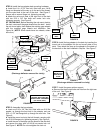
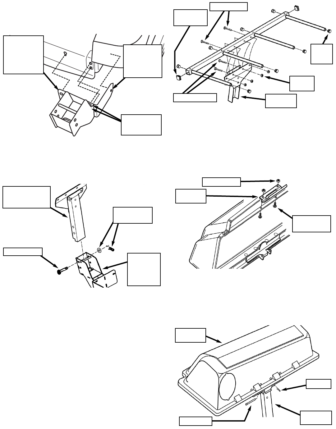
STEP 8: Insert the bagger channel into the grass catcher
support, and secure with two 1/2 x 4-3/16” clevis pins,
washers, and hair pins. See Figure 10.
STEP 9: Install the catcher frame into the top of the bagger
channel, securing with two 5/16 x 2-1/4” hex bolts in the
inner two holes, and two 5/16 x 2” hex bolts in the outer two
holes. See Figure 11. Secure the bolts with four hex center
lock nuts, tightening securely. Also, Insert one square end
cap into each end of the square tube, and one round end
cap into each end of the four round tubes. See Figure 11.
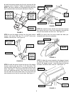
STEP 10: Install the cover handle onto the screen support
bar, behind the front of the cover assembly, securing with
two pan head screws and lock nuts. See Figure 12.
NOTE: On some units, the cover handle has been pre-
assembled onto the cover assembly.
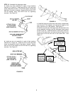
STEP 11: Attach the cover assembly to the bagger channel
by aligning the holes in the cover hinge with the top set of
holes in the bagger channel. Insert the hinge pin through
the holes, and secure with a hair pin. See Figure 13.
3
FIGURE 10
INSERT CHANNEL
INTO CATCHER
SUPPORT
CATCHER
SUPPORT
(SHOWN
DETACHED
FROM UNIT)
WASHER &
HAIR PIN (2)
CLEVIS PIN (2)
FIGURE 11
BAGGER
CHANNEL
LOCK
NUT (4)
ROUND
END
CAP (8)
FIGURE 12
COVER
HANDLE
LOCK NUT (2)
PAN HEAD
SCREW (2)
2” BOLT (2)
2-1/4” BOLT (2)
FIGURE 9
SECURE WITH
REMOVED
HARDWARE
SECURE WITH
SUPPLIED 5/16
x 3/4” HEX
WASHER HEAD
BOLT &
FLANGE NUT
SECURE WITH
SUPPLIED 5/16
x 3/4” HEX
WASHER
HEAD BOLT
SQUARE
END CAP (2)
FIGURE 13
BAGGER
CHANNEL
COVER
ASSEMBLY
HAIR PIN
HINGE PIN