26
Section 4 - ADJUSTMENTS & REPAIR
WARNING
DO NOT attempt any adjustments, maintenance,
service or repairs with the engine running. Stop
engine. Stop blade. Engage parking brake. Remove
key. Remove spark plug wire from spark plug and
secure away from plug. Engine and components
are HOT. Avoid serious burns, allow all parts to
cool before working on machine. Fuel Filler Cap
and Vent must be closed securely to prevent fuel
spillage.
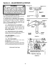
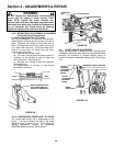
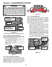
FIGURE 4.15
(Right side shown; fuel tank removed for clarity)
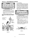
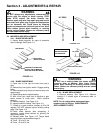
4.6.2. Neutral Return Spring Adjustments
When the motion control levers are released, return
springs assist them back to the neutral position. See
Figure 4.16. To adjust spring tension:
1. If a stronger return is desired, tighten the nyloc
nut atop the return spring rod.
2. If a weaker return is desired, loosen the nyloc
nut atop the return spring rod.
NOTE: Be sure to adjust left and right return
springs equally.
FIGURE 4.16
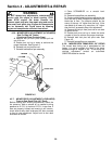
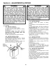
4.6.3. Motion Control Lever Alignment
Correctly aligned Motion control levers will propel the
mower forward in a straight line when levers are equally
engaged into drive. See Figure 4.17. If one
transmission engages before another, loosen the lever
adjustment screws, and adjust the lever forward or
backward until levers are aligned. See Figure 4.18.
FIGURE 4.17
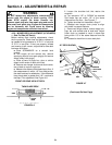
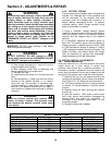
4.6.4. Tracking Adjustments
When both motion control levers are fully engaged in
forward drive, the machine should move in a straight
line. If the machine tracks (veers) left or right, a
tracking adjustment must be made. Each motion
control lever is equipped with a tracking adjustment
plate. See Figure 4.18. Moving the plate forward or
backward adjusts the machine’s tracking:
1. If mower tracks to the left, loosen the two torx
screws on the left adjustment plate, slide plate
forward approximately 1/8”, and retighten screws.
(If plate is already as far forward as it can go,
loosen the right plate and slide back 1/8”.) Check
machine tracking and repeat as needed.
2. If mower tracks to the right, loosen the two torx
screws on the right adjustment plate, slide plate
forward approximately 1/8”, and retighten screws.
(If plate is already as far forward as it can go,
loosen the left plate and slide back 1/8”.) Check
machine tracking and repeat as needed.
3. In cases of severe tracking, one plate may
need to be moved fully back and the other moved
fully forward.
FIGURE 4.18
TURN CLOCKWISE IF WHEEL
TURNS IN REVERSE,
COUNTERCLOCKWISE IF
WHEEL TURNS FORWARD
PIVOT BRACKET (LEVER
MUST BE IN NEUTRAL
LOCK POSITION
)
CONTROL
ROD
ROD
FITTING
HAIR PIN
TRACKING
ADJUSTMENT
PLATE
ADJUST
TENSION
ADJUSTING
NUT
=
=
LEVER
ALIGNMENT
SCREWS
ADJUST UNTIL
LEVERS ARE
ALIGNED
NEUTRAL
RETURN
SPRINGS


