


20
Initial
Assembly
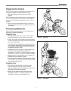
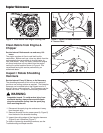
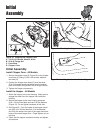
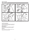
Figure 18. Installing the Chipper Cone
A. 1/4-20 x 3/4 Screw, Washer, & Nut
B. 5/16-18 Flange Nut
C. Cone Base
D. Chipper Cone
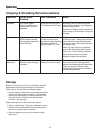
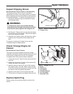
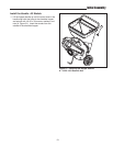
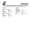
Figure 19. Attaching the Hopper
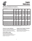
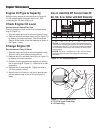
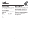
Figure 20. Installing Hardware Inside the Hopper
Initial Assembly
Install Chipper Cone - All Models
1. Secure the chipper cone (D, Figure 18) to the chipper
cone base (C) using 1/4-20 x 3/4 screws, washers,
and nuts (A).
2. Position the chipper cone base (C) over the three
5/16-18 threaded studs protruding from the engine
plate, and attach using three 5/16-18 flange nuts (B).
3. Tighten the flange nuts securely.
Install the Hopper - All Models
1. Attach the hopper to the rotor housing. Make sure to
engage the metal lip of the hopper liner inside the
housing.
2. Secure the hopper to the rotor housing using two
5/16 x 1/2 hex head bolts and two 5/16 flat washers
(Figure 19). Do not tighten hardware at this time.
3. See Figure 20. From the inside of the hopper install
one 5/16-18 x 3/4 hex head bolt, 5/16 lockwasher,
and 5/16 flat washer into each of the upper and lower
holes of the metal hopper liner. Finger tighten only at
this time.
4. Check that the hopper is seated correctly and tighten
all hardware.
A
D
B
C