


2
Installation Instructions Hitch & Tube Group
Form No. 1727434-00
Rev. 07/2004
© 2004 Simplicity Manufacturing, Inc. All Rights Reserved
TP 200-4128-00-AT-SMAN
MANUFACTURING, INC.
500 N Spring Street / PO Box 997
Port Washington, WI 53074-0997 USA
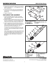
Figure 4. Discharge Tube Installation
A. Decal E. Truss Head Screw
B. Discharge Tube F. Hose
C. Locknut, Hose G. Clamp
D. Washer H. Turbo Discharge
G
H
F
A
B
C
D
E
F
G
2. Connect the inner hitch (B, Figure 3) to the cross bar
hitch (C) using 3/8-16 x 1-1/4 carriage bolts (D) and
3/8-16 locknuts (A).
3. Connect the cross bar hitch (C) to the brackets (E)
using 3/8-16 x 1-1/4 carriage bolts (D) and 3/8-16
locknuts (A).
4. Tighten all hardware.
DISCHARGE TUBE ASSEMBLY
1. Connect the flexible hose (F, Figure 4) and clear
plastic discharge tube (B). The two should overlap
by approximately 2”.
2. Secure the tubes using truss head screws (E), wash-
ers (D), and locknuts (C). Insert the screws from the
inside out and poke them through the flexible hose.
3. Insert the upper end of the clear tube into the cart
sleeve. Slide the flex hose (F) over the turbo (H) and
secure with the large hose clamp (G). The hose
should overlap the turbo discharge by 2”-3”.
The clamp screw should be positioned to the inside
as shown to prevent accidental impact and removal
of the clamp.
Check that the upper end of the clear tube (B, Figure
4) is not contacting the top of the collector cover. If
necessary, cut off the clear tube flush with the con-
necting sleeve (See Wide Body Cart Operators
Manual).
Figure 3. Hitch Installation
A. Locknut,3/8-16 D. Carriage Bolt, 3/8-16 x 1-1/4
B. Inner Hitch E. Bracket
C. Cross Bar Hitch
D
C
A
B
A
D
E
E