


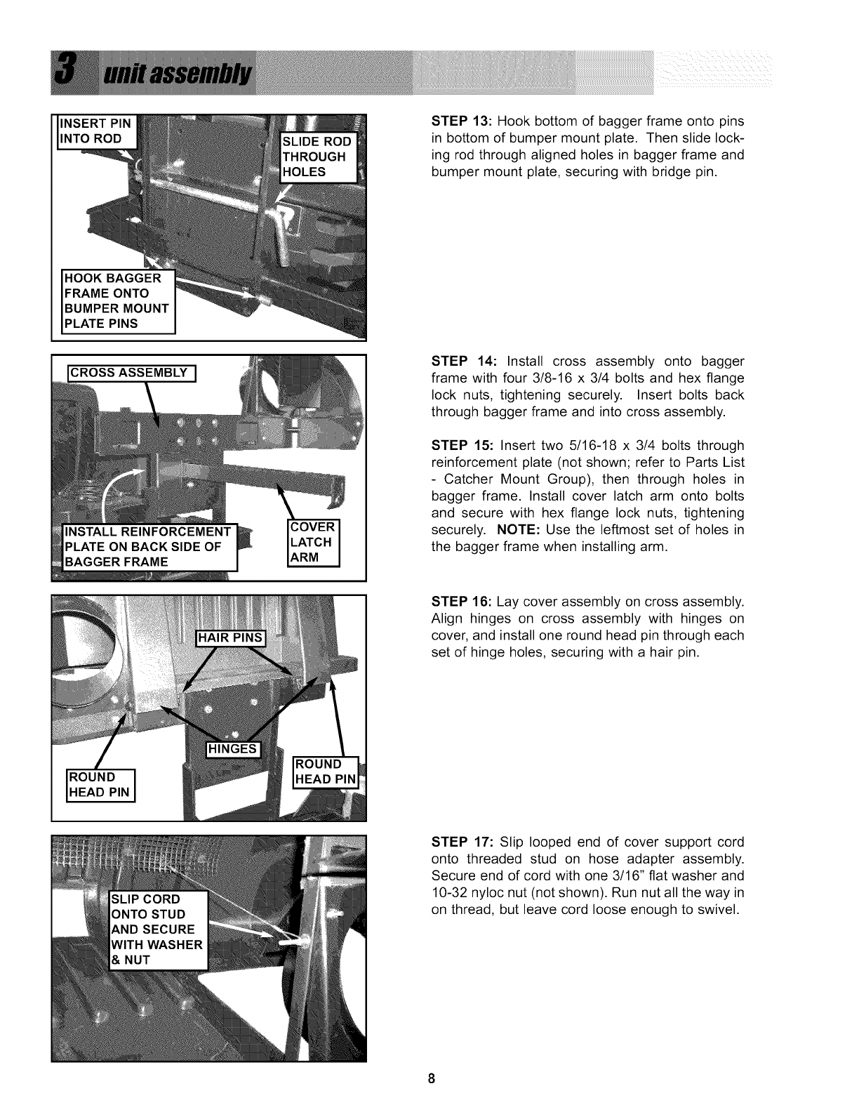
INSERT PIN
INTO ROD
HOOK BAGGER
FRAME ONTO
BUMPER MOUNT
PLATE PINS
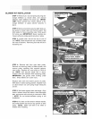
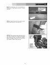
STEP 13: Hook bottom of bagger frame onto pins
in bottom of bumper mount plate. Then slide lock-
ing rod through aligned holes in bagger flame and
bumper mount plate, securing with bridge pin.
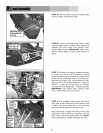
CROSS ASSEMBLY
STEP 14: Install cross assembly onto bagger
frame with four 3/8-16 x 3/4 bolts and hex flange
lock nuts, tightening securely. Insert bolts back
through bagger frame and into cross assembly.
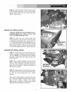
STEP 15: Insert two 5/16-18 x 3/4 bolts through
reinforcement plate (not shown; refer to Parts List
- Catcher Mount Group), then through holes in
bagger frame. Install cover latch arm onto bolts
and secure with hex flange lock nuts, tightening
securely. NOTE: Use the leftmost set of holes in
the bagger frame when installing arm.
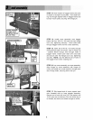
STEP 16: Lay cover assembly on cross assembly.
Align hinges on cross assembly with hinges on
cover, and install one round head pin through each
set of hinge holes, securing with a hair pin.
ROUND IHEAD PIN
STEP 17: Slip looped end of cover support cord
onto threaded stud on hose adapter assembly.
Secure end of cord with one 3/16" flat washer and
10-32 nyloc nut (not shown). Run nut all the way in
on thread, but leave cord loose enough to swivel.
8