


OPERATOR’S MANUAL and DEALER SET-UP for SNAPPER
73” MOWER for OUT FRONT Z-RIDER
INTRODUCTION: These instructions cover set-up of the Snapper 73” Mower for the Out Front Z-Rider.
The linkage on this mower has been designed to allow the use of the electric actuator on the deck to assist in
attaching the mower to the power unit. Follow and complete each step carefully.
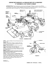
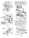
FIGURE 1 - NOMENCLATURE
STEP 1: Remove Mower Unit and Components from
the carton(s).
STEP 2: Adjust Rear Casters to lowest position by
removing Lynch Pins and placing Spacers on bottom
side of Tube. See Figure 2.
STEP 3: Remove the nuts and bolts from the Front
Caster Wheel Support Arms. See Figure 3.
STEP 4: Extend the Front Caster Wheels out until they
are aligned with the last set of holes. Reinstall nuts and
bolts. See Figure 3.
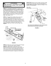
STEP 5: Check pin location at the lower end of the
Deck Stabilizer Channels. It should be in the middle
hole of the bracket. See Figure 4.
STEP 6: Remove contents of hardware bag which
includes (1) #9 Woodruff Key and (2) 3/8”-16 x 3/8” Set
Screws. Place Woodruff Key onto Gear Box Shaft on
mower deck. Slide Power Transfer Shaft over Gear Box
Shaft and make sure Woodruff Key remains in its
position. See Figure 5.
COPYRIGHT © 2001
SNAPPER INC.
ALL RIGHTS RESERVED
FIGURE 2
MANUAL NO. 7-3720 (Rev. 1, 7/25/01)
TUBE
SPACERS
(ON BOTTOM)
LYNCH PIN
REAR CASTER
DECK LIFT
WIRING
HARNESS
PLUG
REAR
CASTER
WHEELS
LINEAR
ACTUATOR
HEIGHT OF CUT
INDICATOR
DECK FRAME
ASSEMBLY
FRONT CASTER WHEELS
(Shown Fully Extended)
DISCHARGE
CHUTE
SIDE
ROLLER
CENTER DECK
ROLLER
LIFT ARM
PIN