


18
Section 4 - ADJUSTMENTS & REPAIR
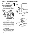
WARNING
Before attempting any adjustments or repairs, STOP
the engine, remove the spark plug wire from the
spark plug and secure wire away from plug. Wear
heavy leather gloves when handling or working around
cutting blades. Blades are extremely sharp and can
cause severe injury. Never use a cutting blade that
shows signs of excessive wear or damage.
4.4.1. Engine Drive Belt Replacement
(Standard and Stretch Type Belts)
(Continued From Previous Page)
IMPORTANT: DO NOT tip machine with carburetor or
spark plug down. Oil from crankcase will saturate the air
filter and cause the engine to be hard to start or not start
at all. If contamination does occur, the air filter will have to
be replaced.
3. Remove the driven disc. Refer to Section on
“Replacing Rubber Driven Disc Ring” for driven disc
assembly removal procedure.
4. Tilt mower up on its rear wheels and remove
blade and blade hub. Assistance from another
person may be necessary to hold mower in the
tilted position.
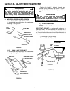
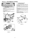
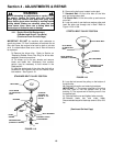
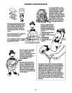
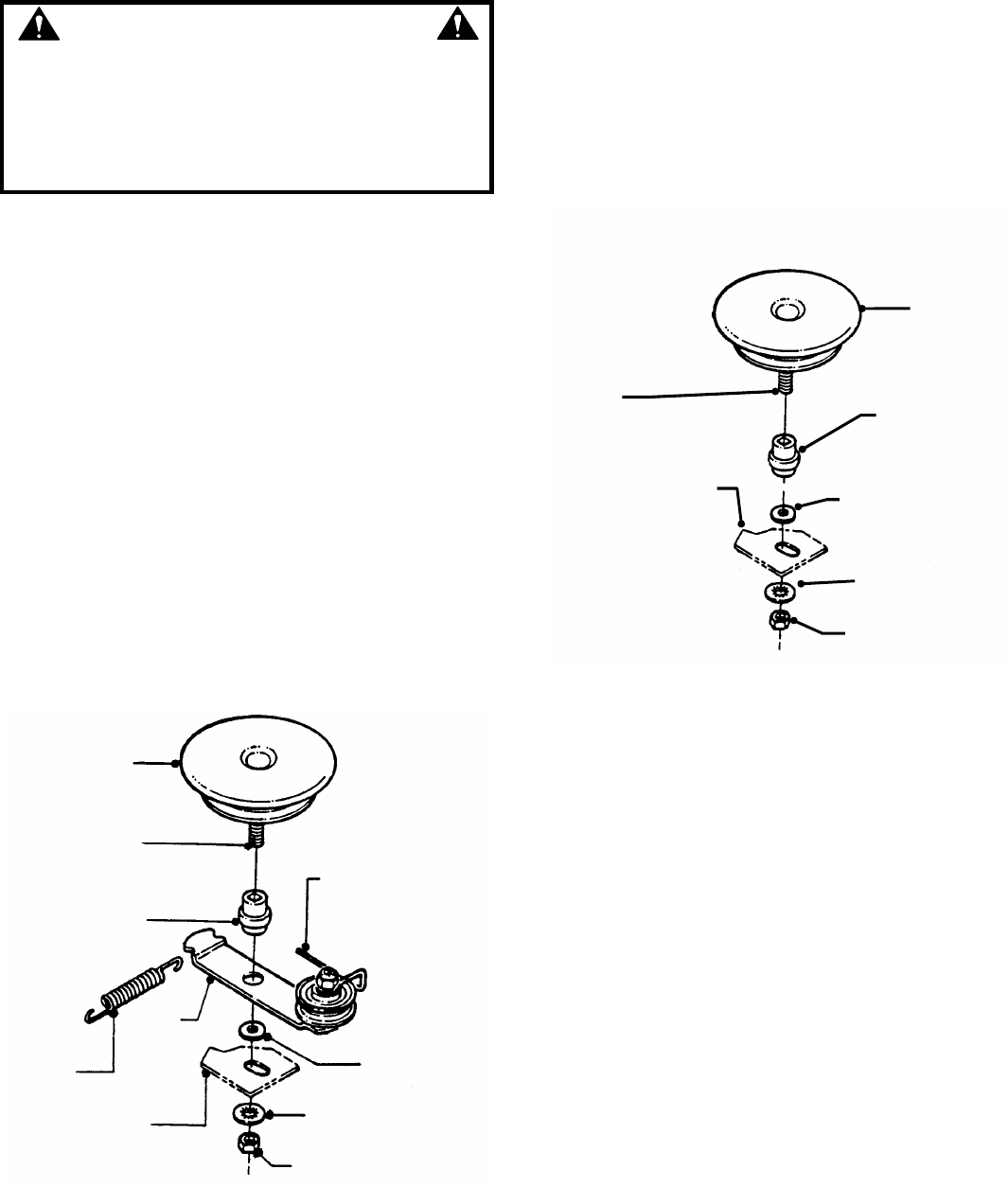
5. Hold the slotted end of the drive disc bolt with a
screwdriver and remove the nut and internal tooth
lock washer. See Figure 4.19.
STANDARD BELT PULLEY POSITION
FIGURE 4.19
6. Remove the belt cover located under deck.
7. Standard Belt: Lift the drive disc off the idler
arm and remove worn belt.
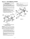
7.A. Stretch Belt: Lift the drive disc up and remove
worn belt.
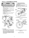
8. Loop one end of new belt over engine pulley and
insert the other end through slot in deck. Refer to
Figure 4.18 & 4.18A.
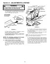
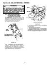
STRETCH BELT PULLEY POSITION
FIGURE 4.19
9. Loop the belt around the pulley on the bottom of
the drive disc.
10. Reinstall drive disc and retaining hardware.
IMPORTANT: 1) The square shoulder of the drive
disc bolt must fit into the square hole of the
bushing. 2) The square end of bushing must fit into
the bracket slot.
11. Reinstall belt cover and tighten bolts securely.
12. Reinstall blade hub and cutter blade.
Recommended torque for blade cap screw is 30 to 40 ft.
lbs.
(Continued On Next Page)
DRIVE DISC
SLOT IN END
OF DRIVE DISC
BOLT
BUSHING
POSITION
SCRAPER TO
CLEAR “V” OF
PULLEY
BOLT RETAINER
IDLER
SPRING
IDLER
ARM
DECK BRACKET
(PARTIALLY SHOWN)
INTERNAL TOOTH
LOCKWASHER
NUT
DRIVE DISC
SLOT IN END
OF DRIVE DISC
BOLT
BUSHING
BOLT RETAINER
DECK BRACKET
(PARTIALLY SHOWN)
INTERNAL TOOTH
LOCKWASHER
NUT