


17
Section 4 - REPAIR & ADJUSTMENTS
WARNING
DO NOT attempt any maintenance, adjustments or
service with engine and blade running. STOP engine
and blade. Disconnect spark plug wire and secure
away from spark plug. Engine and components are
HOT. Avoid serious burns, allow sufficient time for
all components to cool.
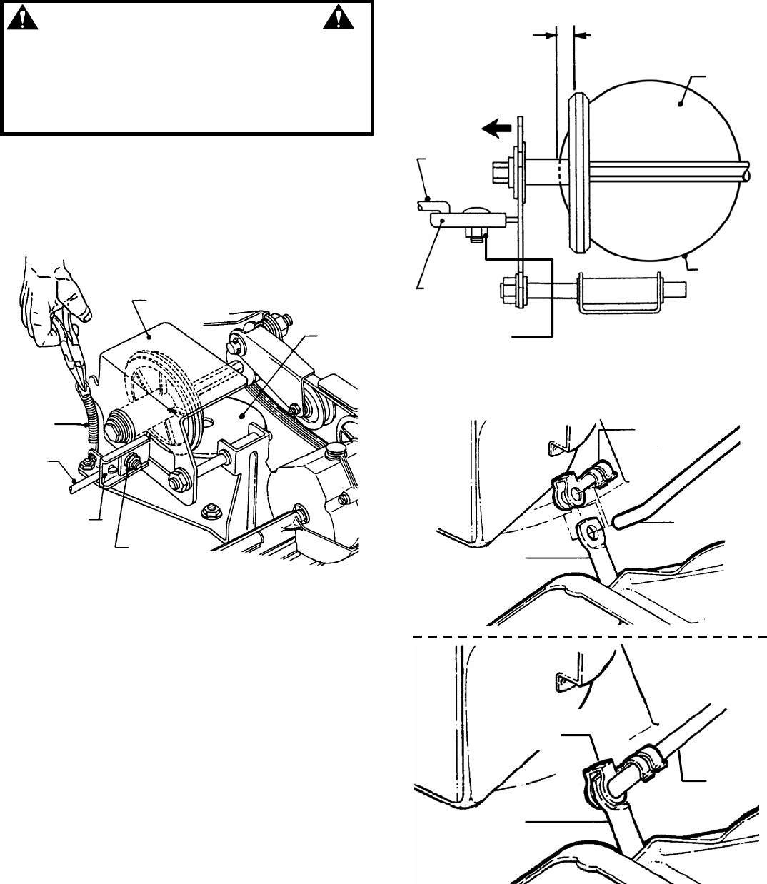
4.3.3. DRIVEN DISC ADJUSTMENT
(Continued From Previous Page)
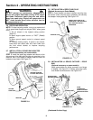
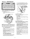
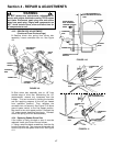
2. Remove driven disc spring from driven disc
assembly. Loosen connector hex nut. See Figure
4.9.
FIGURE 4.9
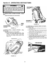
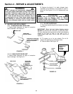
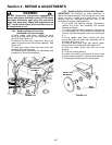
3. Slide driven disc assembly over to 1/8” from
outside edge of drive disc. Maintaining the 1/8”
measurement, remove any looseness from the
linkage. This can be done by holding the transfer
rod and applying pressure to the left (as viewed
from operators position). Then retighten the
connector hex nut securely. See Figure 4.10. Move
ground speed control to the first speed position,
then back to the sixth speed position. Recheck the
1/8” measurement described previously. Reinstall
driven disc spring to driven disc assembly.
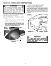
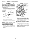
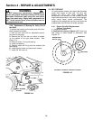
4.3.4. Replacing Rubber Driven Disc
If the rubber is badly chunked or worn it must be
replaced. Install new Driven Disc as follows:
1. Using a small flat blade screwdriver, free the clip
from the transfer rod. Then remove the transfer rod
from the clip and the speed control rod. See Figure
4.11.
FIGURE 4.10
FIGURE 4.11
1/8” MEASUREMENT TO
OUTSIDE EDGE OF DRIVE
DISC
DRIVE
DISC
SLIDE DRIVEN
DISC ASSEMBLY
TOWARD OUTSIDE
EDGE
TRANSFER
ROD
CONNECTOR
CONNECTOR
HEX NUT
OUTSIDE
EDGE
DRIVEN DISC
ASSEMBLY
DRIVE
DISC
DRIVEN DISC
SPRING
TRANSFER
ROD
CONNECTOR
CONNECTOR
HEX NUT
CONNECTOR
CLIP
SPEED
CONTROL
ROD
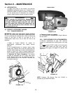
TRANSFER
ROD
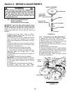
SPEED
CONTROL
ROD
TRANSFER
ROD
CONNECTOR
CLIP
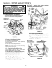
REINSTALLED CLIP
AND TRANSFER ROD