


37
English
en
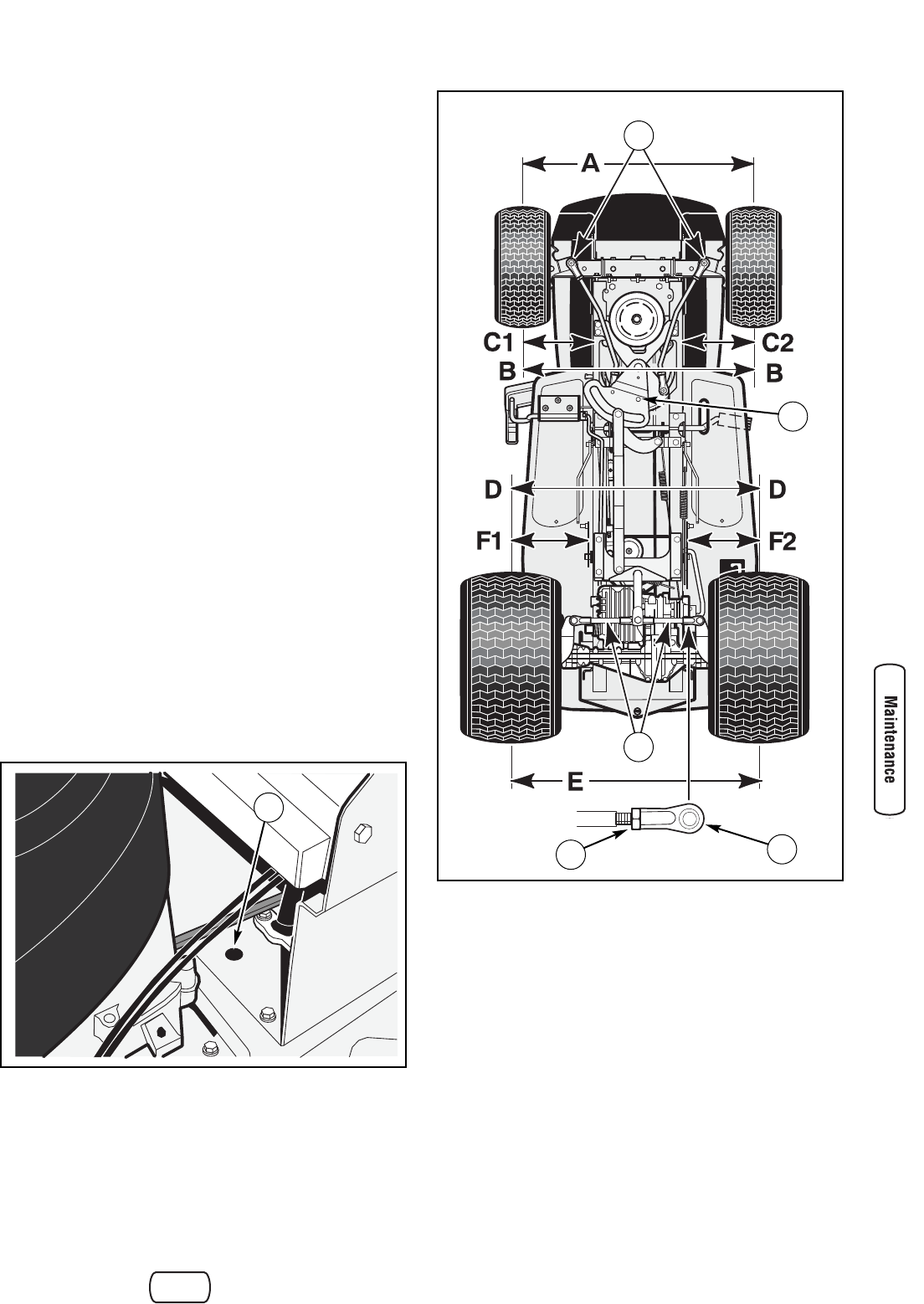
Wheel Alignment
Check the alignment of the wheels after the removal or
replacement of any steering system parts as follows:
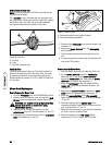
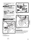
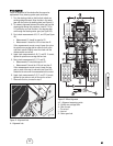
1. Turn the steering wheel so that the front wheels are
pointing straight forward. Align the hole in the sector
gear with the hole in the steering plate (see Figure 41).
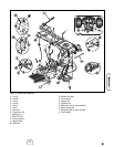
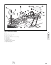
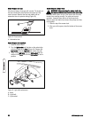
2. To maintain alignment between the sector gear and the
steering plate during this procedure, insert a 7/16 to
1/2 inch bolt or pin into the hole in the steering plate
and through the steering sector gear (see Figure 42).
3. First, check measurements A, B, C1, and C2 (see Figure
42).
• Measurement C1 should be equal to C2.
• Measurement A should be 1/4 inch less than B.
If the measurements are not correct, loosen the nut on
the spindle arm carriage bolt on either the left or the
right front spindle. Slightly move the wheel until the
measurements are correct.
4. Again check measurements A, B, C1, and C2. If correct,
tighten the spindle arm carriage bolt and nut.
5. Next, check measurements D, E, F1 and F2.
• Measurements F1 should be equal to F2.
• Measurement D should be 1/16 inch less than E.
If the measurements are not correct, loosen the jam
nuts on each of the rear tie rod ends (see Figure 42).
Rotate the tie rods until the measurements are correct.
6. Again check measurements D, E, F1 and F2. If correct,
tighten the jam nuts on each of the rear tie rod end.
7. Remove the bolt or pin used in step 2.
Figure 41: Alignment hole
A - Alignment hole
Figure 42: Wheel alignment
A-F - Alignment measuring points
G - Spindle arm carriage bolts
H - Rear tie rods
I - Tie rod end
J - Jam nut
K - Sector gear hole
A
G
H
J
I
K