18
Section 4 - ADJUSTMENT & REPAIR
WARNING
DO NOT attempt any adjustments, maintenance or
service with the engine or blade running. STOP blade.
STOP engine. Set brake. Remove key. Remove spark
plug wire from spark plug and secure wire away from
spark plug. Engine and components can be extremely
hot. Avoid burns by allowing engine and components
sufficient time to cool. If deck front to rear level is not
correct, this could cause blade belt problems.
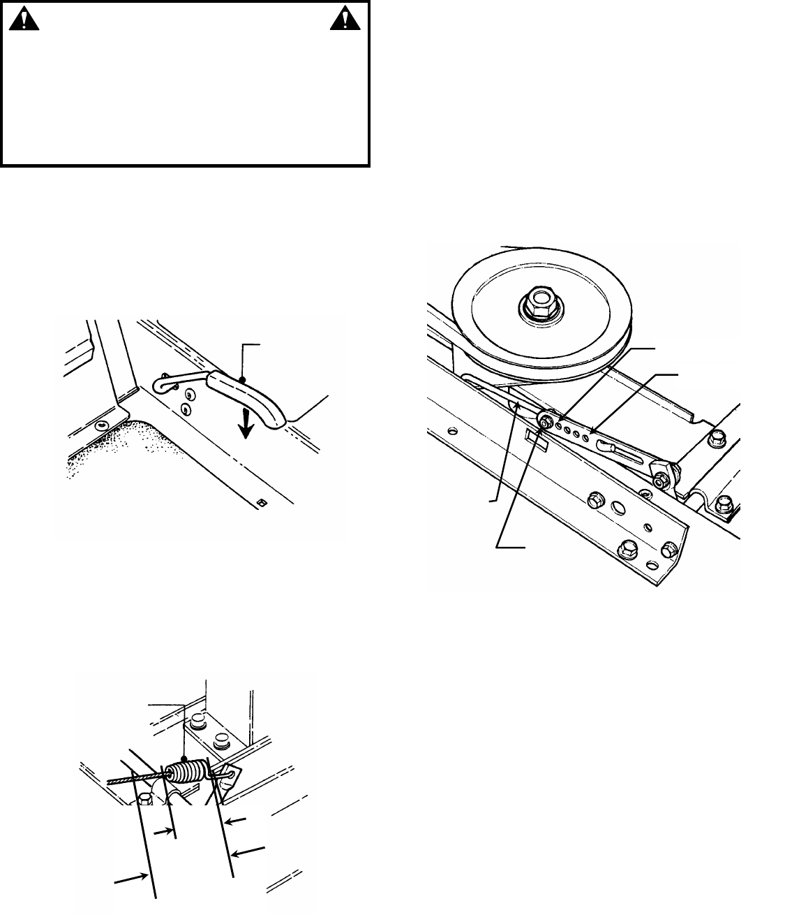
4.2.2. BLADE BELT ADJUSTMENT – 33” DECK
1. Move tractor to a firm, level surface.
2. Turn engine "OFF". Remove key.
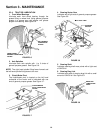
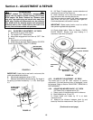
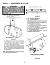
3. Move blade engagement lever down to "OFF". See
Figure 4.2.
4. Place deck in mid cutting position.
5. Check front to rear level. Refer to Section “33 DECK
LEVEL ADJUSTMENT (FRONT TO REAR)”.
FIGURE 4.2
IMPORTANT: If deck front to rear level is not correct, this
could cause blade belt problems.
6. Move blade engagement lever to "ON".
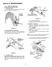
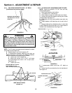
7. Measure blade cable extension spring. The length of
the spring (x) should increase by 1” (+/-1/8”). See Figure
4.3.
FIGURE 4.3
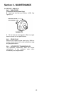
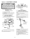
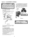
8. (33" Deck) To adjust tension, remove extension rod
mounting bolt and nut. See Figure 4.4.
9. Move extension rod to next hole towards rear of
deck and secure with mounting bolt and nut.
10. Measure extension spring with blade engagement
lever in the "ON" and "OFF" positions. See Figure 4.3.
Continue adjustment until tension is correct.
IMPORTANT: Blade brake function must be verified
after performing blade belt adjustment.
11. Check blade brake. Refer to Section “CHECK
BLADE BRAKE”. Blades must stop rotating in 5
seconds or less when turned off.
FIGURE 4.4
4.2.3. BLADE BELT ADJUSTMENT – 38” DECK
The blade belt on the 38” deck requires no tension
adjustment. If the belt becomes worn or damaged it must
be replaced. Refer to Section “BLADE BELT REMOVAL &
REPLACEMENT”.
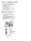
4.2.4. ADJUSTING MOWER BLADE – 33” DECK
(33" Decks Only; no adjustment for 38")
1. Select a point on the deck and mark for reference.
2. Mark blade tips as “A” and “B”.
3. Rotate blade until blade tip “A” is at deck
reference mark
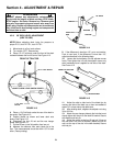
4. Measure the distance between deck lip and
blade tip. Note the measurement. See Figure 4.5.
(Continued on next page)
MOVE BLADE
ENGAGEMENT
LEVER TO “OFF”
BLADE CABLE
EXTENSION
SPRING
X + 1” +/- 1/8”
X
EXTENSION
ROD
LEAST TENSION
MOST TENSION
MOUNTING
NUT & BOLT


