


3 unit assembly
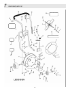
Note: Please refer to Parts List for correct part identification and placement.
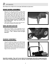
FRONT WHEEL ASSEMBL
Y
• Attach left and right caster brackets to caster wheel
using 3/8-18 x 2-1/4 bolt and lock nut. Insert bolt through
hole in bracket. Place caster wheel onto bolt. Place
other caster bracket onto bolt. Secure with lock nut. Do
not over tighten. Wheel must rotate freely. Place caster
brackets onto the threaded studs located near the dis-
charge on the front of the machine. Place flat washer
and split lock washer on each stud. Note: Angled edge
of mounting brackets should be upwards, with
holes toward bottom. Fasten with two 5/16-18 hex
nuts. Do not tighten.
• Check caster wheel for proper vertical alignment (cam-
ber), adjust as necessary, then tighten nuts.
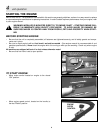
SIDE AIR DEFLECTOR
• Attach side air deflector to top of discharge chute by
aligning holes in deflector with threaded studs in top of
chute snout. Fasten with two 5/16-18 hex nuts and split
lock washers. Note: Deflector should be angled
downward.
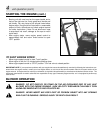
HANDLE ASSEMBLY
• The upper handles are shipped in the folded storage
position. To unfold, loosen two handle knobs and rotate
up to the operating position. The upper handles are
secured with four knobs. Insert two 5/16-18 x 2 curved
head bolts through the handles directly below the two
shipping knobs. Place one internal tooth lock washer on
each of the bolts. Thread knobs onto curved head bolts.
Tighten all four knobs securely.
Assembly complete. Your unit is now ready to be started and checked for proper operation.
Some minor final adjustments may be required; see the Maintenance portion of this manual.
5