


9
Section 3 - ADJUSTMENTS & REPAIR
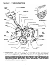
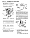
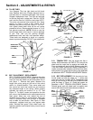
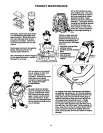
3.4 TILLER TINES
Your Snapper Tiller has right hand and left hand
tines. Replace both tines if blades become bent or
are badly worn or otherwise damaged. Use correct
Snapper replacement tines. The tines are secured
to the tine shaft with a shear bolt, Part No. 2-8725
and Lock Nut Part No. 9-0222 on each side. NOTE:
Two extra nuts and two bolts come with tiller. Keep
spares on hand in case a bolt shears off or
becomes lost while tilling. See Figure 11. DO NOT
over tighten these shear bolts as this will cause
premature failure. (Recommended torque is 5 to 8
foot pounds maximum). NOTE: Failure to use the
correct shear bolts could result in serious damage
to your Tiller. Use only the genuine Snapper
replacement bolts and lock nuts specified above.
These bolts are designed to shear at a specific
stress to prevent damage. DO NOT use substitutes!
FIGURE 11
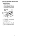
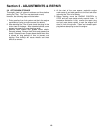
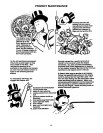
3.5 BELT ADJUSTMENT - REPLACEMENT
BELT TENSION ADJUSTMENT: Remove the cotter
pin that secures clevis pin to left wheel hub. Remove
clevis pin from left wheel hub and slide wheel out on
axle about 1”. Remove belt guard. Measure the
length idler pulley spring at the end of the control
cable in a relaxed position. Then move wheel and
tine control bail up to the handle bar and measure
the extended length of the spring. When properly
adjusted, the spring will extend 1/4” to 1/2”. See
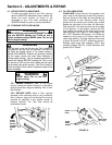
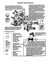
Figure 12. To adjust, loosen and reposition the two
jam nuts on the threaded end of cable located on the
dash panel. Move jam nuts toward the end of
threaded end of cable for more tension. Move jam
nuts in a direction away from the end of threaded
end of cable for less tension. See Figure 13. After
adjustment, retighten both jam nuts against dash
panel. Reinstall belt guard. Slide wheel back into
operating position and reinstall clevis pin and secure
with hair pin.
FIGURE 12
FIGURE 13
3.5.1 TENSION TEST: Start the engine with tiller in
neutral. Shift transmission into FWD & TILL and pull the
wheel and tine control bail up against the handle bar.
Tines and wheels will start to rotate. Release control bail.
Tines and wheels should stop rotating immediately. If
rotation continues after release of control bail then clutch
spring tension is to great and will have to be readjusted
as described in BELT TENSION ADJUSTMENT Section.
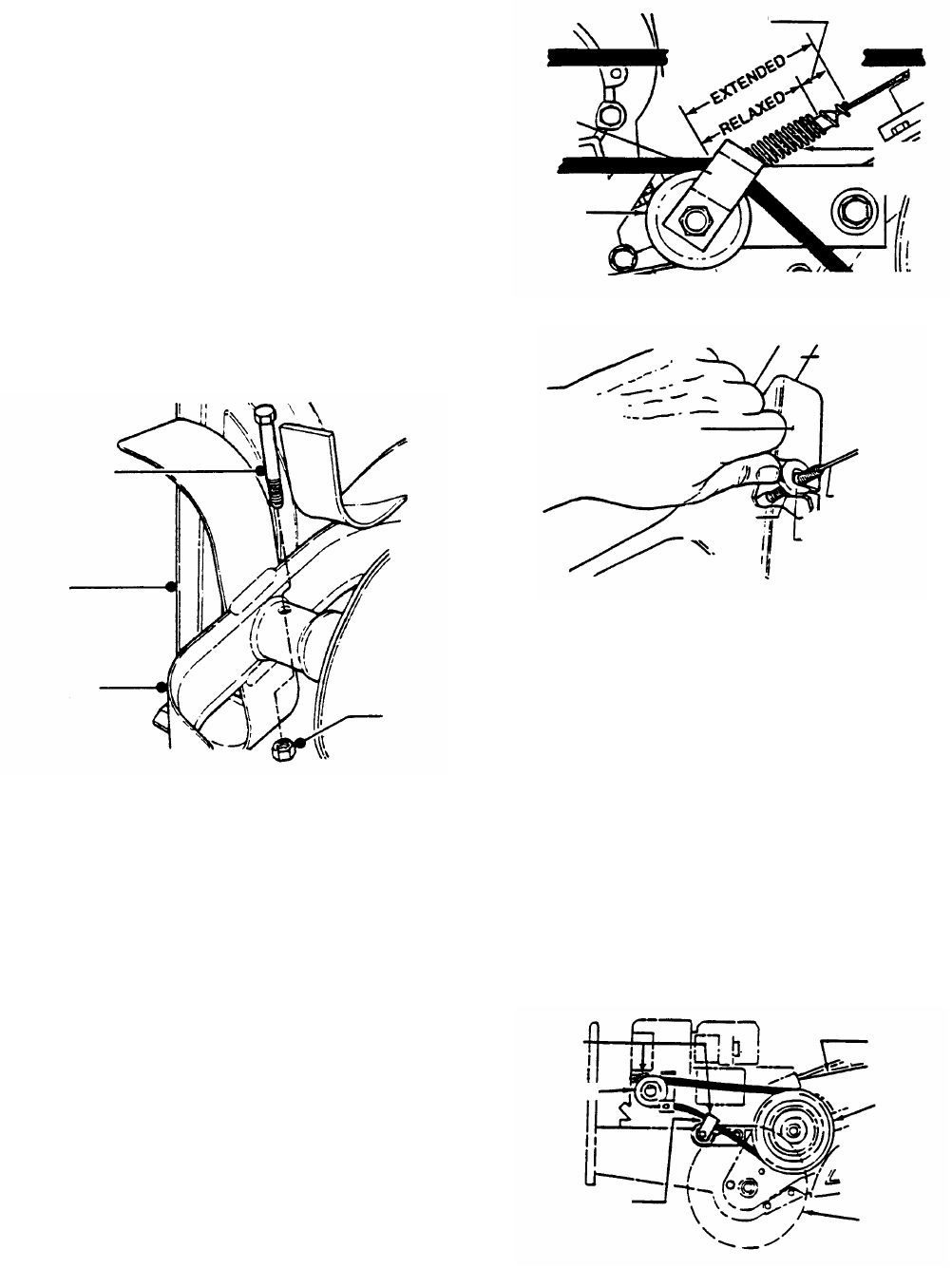
3.5.2 BELT REPLACEMENT: Pull the clevis pin from
the left wheel and slide the wheel out 1”, remove belt
guard and then the old belt. NOTE: Replacement belt
must go over the top of the idler and be within the belt
guide as shown in Figure 14. Check belt tension as
described in BELT TENSION ADJUSTMENT Section.
Reinstall guard, push left wheel back into position and
secure with clevis pin and insert and secure cotter pin.
FIGURE 14
SHEAR BOLT
(TORQUE TO
8 FT. LBS.)
TINE
COVER
TINE
ASSEMBLY
LOCK
NUT
1/4” TO 1/2”
BELT
GUIDE
IDLER
PULLEY
IDLER
PULLEY
SPRING
HANDLEBAR
DASH PANEL
CLUTCH
CABLE
MOVE NUTS
TOWARD END
OF CABLE
FOR MORE
TENSION
LOOSEN
JAM NUTS
BELT
GUIDE
DRIVE
PULLEY
BELT OVER
TOP OF IDLER
SHIFT
LEVER
DRIVEN
PULLEY
REMOVE
LEFT HAND
WHEEL &
BELT
GUARD