


12
Section 4 - REPAIR & ADJUSTMENTS
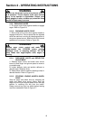
WARNING
DO NOT attempt any adjustments, maintenance,
service, or repairs, with engine running. Stop auger.
Stop engine. Remove key. Disconnect spark plug
wire and secure wire away from spark plug.
4.1 AUGER and WHEEL DRIVE BELT
ADJUSTMENT/REPLACEMENT
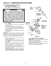
When operating machine release the auger clutch
control. The auger should come to a complete stop in
5 seconds. If auger does not come to a complete stop
in the required time, check and adjust belt tension.
Inspect belts frequently for signs of excessive wear.
Observe drive belts for slippage due to wear when
operating machine. If slippage does occur
adjust/replace as follows.
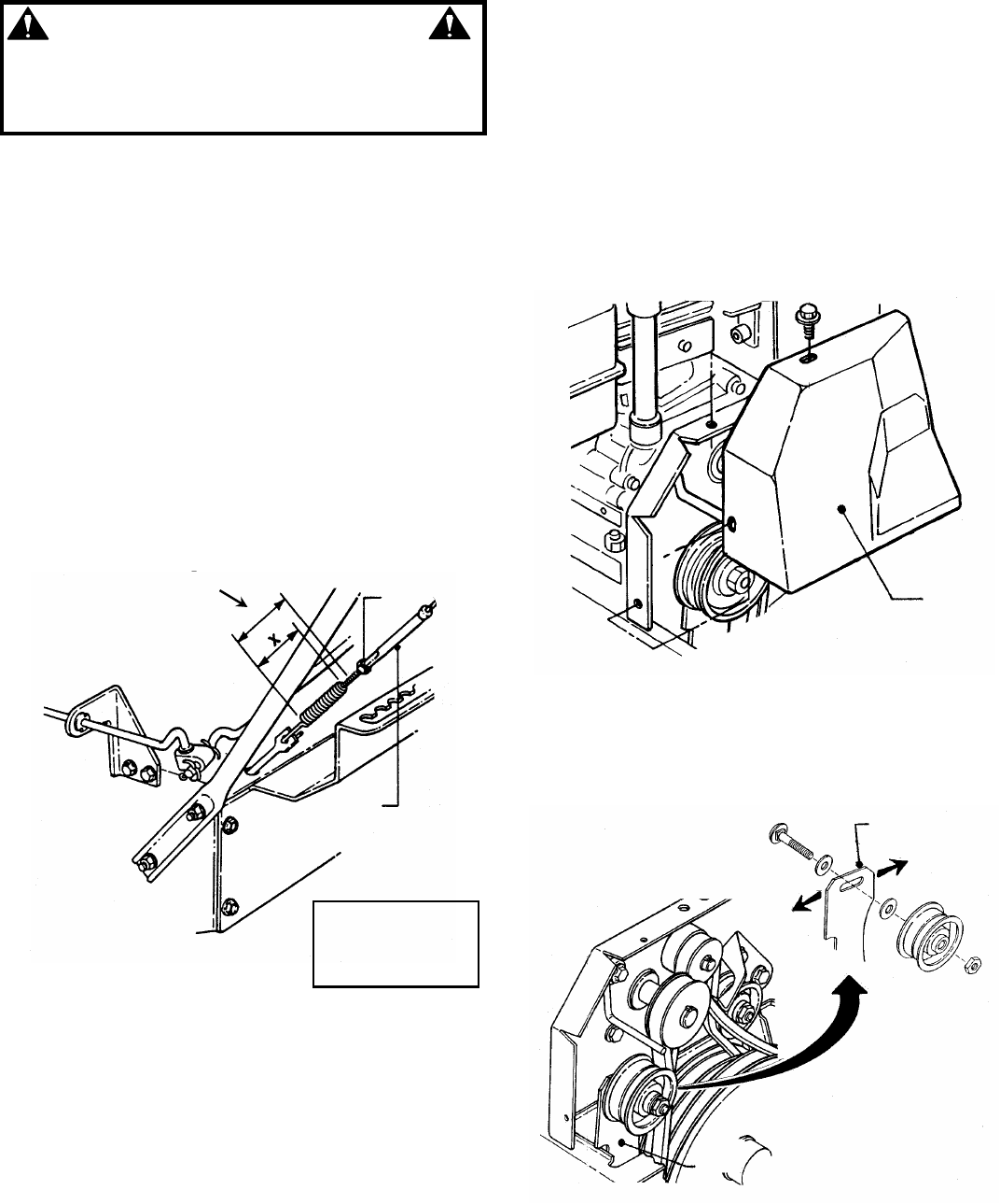
4.1.1. AUGER and WHEEL DRIVE CABLE
ADJUSTMENT
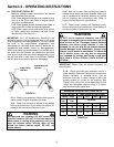
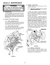
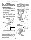
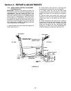
1.Measure control cable extension from a relaxed
position to full extended position. Move control lever
against handle. Measure the overall length of the
spring. The length of the cable spring should increase
by 3/8” when the clutch control lever is depressed. See
Figure 4.1.
FIGURE 4.1
2. Adjust control cable by loosening jam nut at the
upper end of cable. Hold threaded end of cable and
then turn cable clockwise or counter clockwise until
correct extension is achieved. Retighten jam nut.
IMPORTANT: DO NOT over tighten the control cables. The
cables must have slack for the auger/impeller brake to
function properly and for the wheel drive to de-clutch
properly. If the auger control cannot be properly adjusted,
belt adjustment and/or replacement will be required. Refer
to Section “Auger Belt Idler Pulley Adjustment”. If the wheel
drive control cannot be properly adjusted, Refer to Section
“Rubber Drive Disc Replacement”.
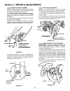
4.1.2. AUGER BELT IDLER PULLEY
ADJUSTMENT
NOTE: To adjust the idler pulley and properly tension
the auger belt, the auger control cable adjustment
must first be loosened as described in the following
step. Cable adjustment must be checked after
completing the idler pulley adjustment.
1. Loosen jam nut at the end of cable. Hold threaded
end of cable and then turn metal housing of cable
counter clockwise until threaded portion of cable is
extracted from metal housing. Reinstall 1/2” of the
threaded portion of cable back into metal housing.
Retighten jam nut.
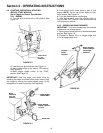
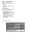
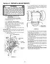
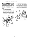
2. Remove belt cover. See Figure 4.2
FIGURE 4.2
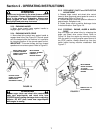
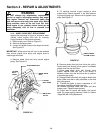
3. Loosen nut and bolt that secures the idler pulley.
Move idler toward belt for more tension or away from
belt for less tension. See Figure 4.3. Retighten bolt and
nut securely.
FIGURE 4.3
CONNECTOR
JAM
NUT
(WHEN ENGAGED)
X+3/8”
SPRING SHOULD
STRETCH 3/8”
WHEN HANDLE IS
DEPRESSED
REMOVE
BELT
COVER
IDLER ARM
IDLER PULLEY ASSEMBLY
SHOWN EXPLODED TO
SHOW DETAIL OF IDLER
ARM SLOT
LEFT
RIGHT
MOVE IDLER PULLEY TO
LEFT INCREASE OR TO
RIGHT DECREASE
TENSION ON BELT
IDLER
ARM