17
Section 4 - ADJUSTMENTS & REPAIR
WARNING
DO NOT attempt any adjustments, maintenance or
service with the engine or blade running. STOP
blade. STOP engine. Set brake. Remove key. Remove
spark plug wire from spark plug and secure wire
away from spark plug. Engine and components can
be extremely hot. Avoid burns by allowing engine
and components sufficient time to cool.
4.2.6. MOWER DECK ADJUSTMENT (LEVELNESS)
Side-To-Side (48” Decks)
(Continued From Previous Page)
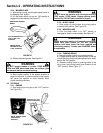
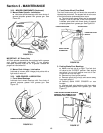
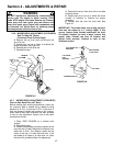
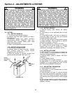
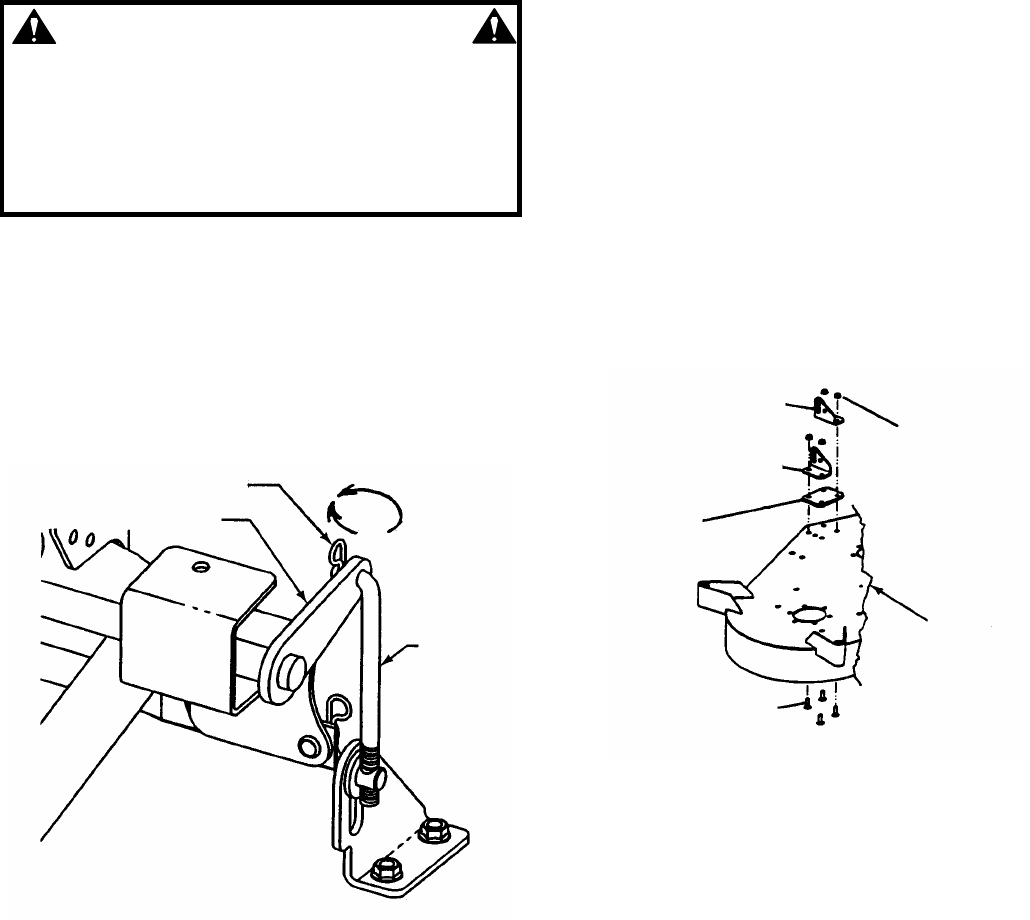
4. Remove hair pin from pivot rod and pull rod
out of lift arm.
5. Rotate pivot rod up or down to achieve the
proper levelness. See Figure 4.5.
6. Reinstall hair pin into pivot rod.
7. Reinstall floor pan.
FIGURE 4.5
4.2.7. MOWER DECK ADJUSTMENT (LEVELNESS)
Front to Rear Deck Pitch (48” Deck)
Before making deck leveling adjustments, check the
tire pressure. Add or release air as needed to bring
pressure to 12 P.S.I. in front and 12 P.S.I. in rear tires. If
tires are properly inflated and mowing is still uneven,
check side-to-side deck levelness first then proceed
to front to rear adjustment. Adjust front to rear deck
levelness as follows:
1. Place YARD CRUISER on a smooth level
surface.
2. Remove floor pan.
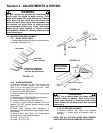
3. Rotate outside blades so tips are pointed to the
front and rear of deck. Measure the distance from
blade tips to floor. The distance should be the
same, or the rear 1/4” lower than the front. If the
rear blade tip is higher or is more than 1/4” lower
than the front, proceed to Step 4 for adjustment.
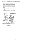
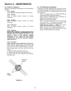
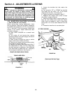
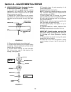
4. Remove the hair pin from pivot rod on one side
of deck at a time.
5. Rotate each pivot rod up or down the same
number of rotations to achieve the proper
levelness.
6. Reinstall both hair pins into pivot rods. See
Figure 4.5.
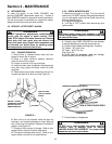
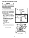
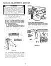
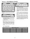
IMPORTANT: The mower deck, over a long period of
time may not adjust to a 4” cutting height. If this
occurs, remove plate located underneath the front
lift bracket. Support the front of deck, remove this
spacer plate, reinstall the front lift bracket, and
tighten bolts securely. Proceed to front to rear
levelness section.
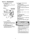
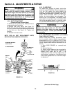
FIGURE 4.6
HAIRPIN
LIFT ARM
PIVOT ROD
R.H. FRONT LIFT
BRACKET
L.H. FRONT
LIFT
BRACKET
CARRIAGE BOLTS
HEX FLANGE
LOCK NUTS
48” DECK


