


18
Section 3 - MAINTENANCE
3.6 DECK REMOVAL
(Continued From Previous Page)
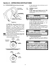
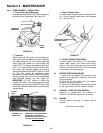
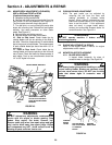
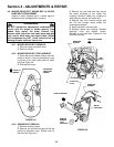
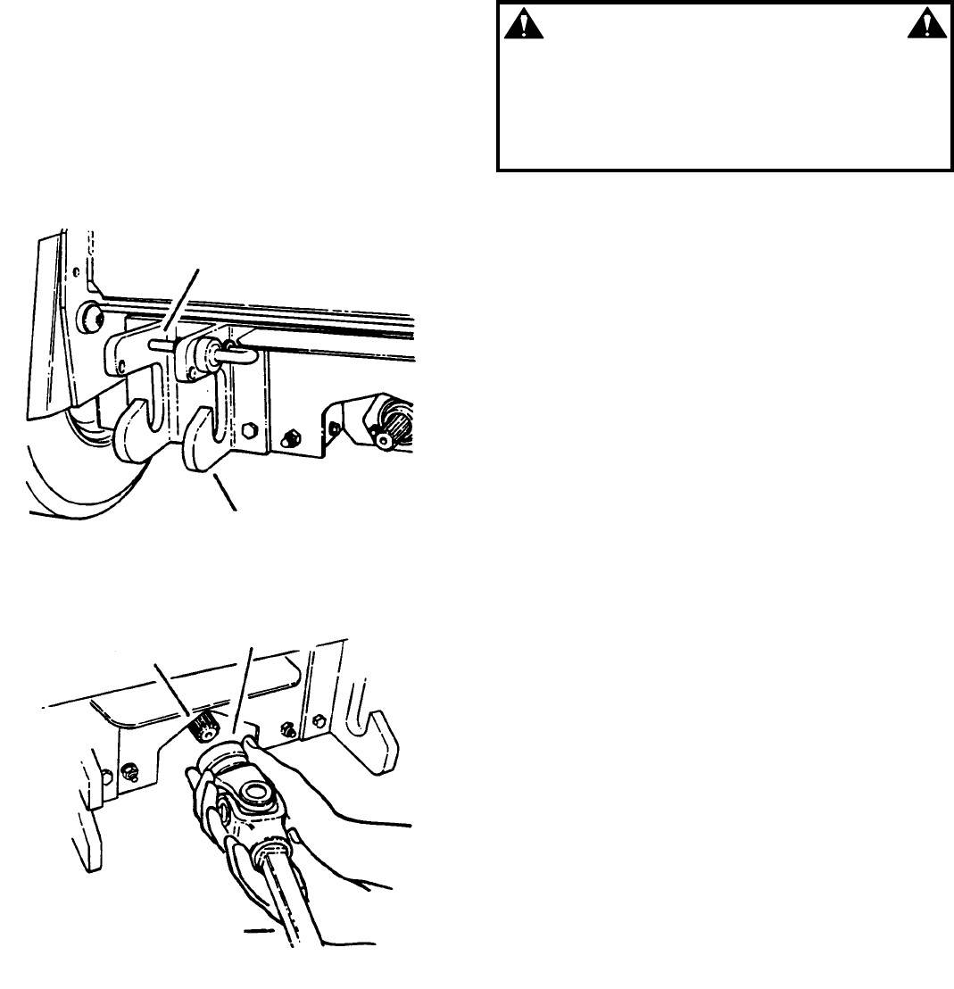
4. Rotate spring loaded hitch latch pins
(Located on both hitch plates) to the unlatched
position. See Figure 3.10.
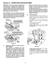
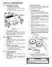
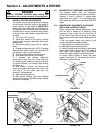
5. Move deck lift switch as if to lower deck and
the lift arm will move up in the hitch plates. The
lift arm needs to be high enough to clear the
hitch plates when power unit is driven
backward away from mower deck. See Figure
3.9.
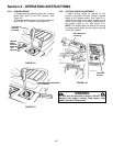
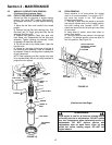
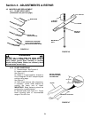
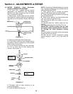
6. Pull lock collar back and slide power
transfer shaft away from power take off (PTO)
shaft. See Figure 3.11.
7. Disconnect wiring harness from mower deck.
8. Start power unit. Disengage parking brake.
Carefully move power unit backward away from
mower deck.
FIGURE 3.10
FIGURE 3.11
3.7 POWER TRANSFER SHAFT REMOVAL
Engage parking brake. Turn engine “OFF” and
remove key. The power transfer shaft connects
the power unit to the mower deck. The shaft is
telescoping for easy removal. Slide locking collar
back toward mower deck and shaft will slide off.
See Figure 3.11.
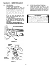
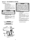
WARNING
DO NOT attempt any maintenance, adjustments or
service with engine running. STOP engine. STOP
blades. Set brake. Remove key. Remove spark plug
wires and secure away from spark plugs. Engine
and components are HOT. Avoid serious burns,
allow sufficient time for all parts to cool.
NOTE: DECK LIFT ARM SHOWN REMOVED FOR
CLARITY. DECK WOULD NOT BE REMOVED AT THIS
TIME IN DECK REMOVAL PROCEDURE.
HITCH LATCH PIN SHOWN IN
UNLATCHED POSITION
HITCH
PLATE
POWER
TRANSFER
SHAFT
LOCK COLLAR
PULL LOCK
COLLAR
BACKWARDS
POWER
TAKE OFF
SHAFT