


18
Section 4 - ADJUSTMENTS & REPAIR
WARNING
DO NOT attempt any adjustments, maintenance,
service or repairs with the engine running. Stop
engine. Stop blade. Engage parking brake. Remove
key. Remove spark plug wire from spark plug and
secure away from plug. Engine and components are
HOT. Avoid serious burns; allow all parts to cool
before working on machine. Fuel Filler Cap and Vent
must be closed securely to prevent fuel spillage.
4.2 ENGINE ADJUSTMENTS & REPAIR
Refer to the engine owner’s manual for those adjustments
and/or repairs that can be made by the owner.
4.3 MOWER DECK & COMPONENT ADJUSTMENTS
The following mower deck and component adjustments
and repairs can be made by the owner. However, if there
is difficulty in achieving these adjustments and repairs, it is
recommended that these repairs be made by an
authorized SNAPPER dealer.
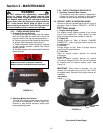
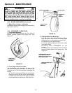
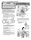
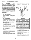
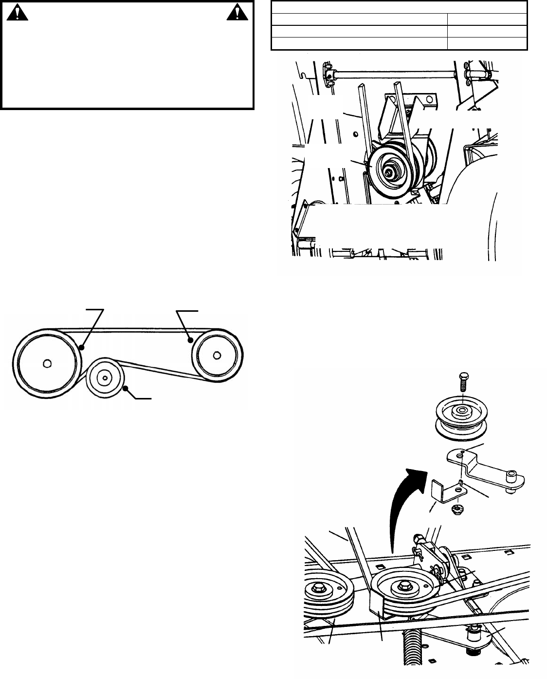
4.3.1. MOWER DRIVE BELT ADJUSTMENT
The 33” mower deck drive belt does not require any
adjustment. If the belt does not drive blade
properly, replace belt as needed. Refer to Section
“BELT REPLACEMENT”. Belt routing shown on
this page. See Figure 4.2.
FIGURE 4.2
4.3.2. MOWER DRIVE BELT REPLACEMENT
Inspect mower drive belt. Replace belt if signs of
excessive wear and/or damage are present.
4.3.3. BELT REMOVAL
1. Remove footrest/floor pan assembly. Refer to
Section “FOOTREST REMOVAL”.
2. Remove old belt.
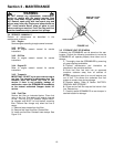
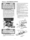
4.3.4. BELT REPLACEMENT
1. Route new belt around electric clutch pulley.
See Figure 4.3.
2. Route belt around stationary idler.
3. Remove spring that is connected to idler pulley.
Loosen nut and bolt that secures idler pulley to idler
arm. Route belt between belt guide and idler pulley.
4. Route belt onto spindle pulley. Make sure belt is
inside spindle pulley belt guide.
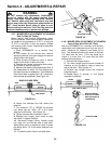
BELT REPLACEMENTS
Engine to Hydro Pumps (All Models) Part No. 4-1823
Engine to Electric Clutch (All Models) Part No. 2-9117
Electric Clutch to Mower (33” Decks) Part No. 3-5389
FIGURE 4.3
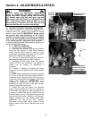
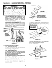
5. Reinstall idler pulley spring. See Figure 4.4.
NOTE: The idler belt guide should be positioned so
the locator tab fits into the corresponding hole found
on the idler arm. See Figure 4.4. Tighten bolt
securely.
6. Reinstall footrest/floor pan assembly.
FIGURE 4.4
MOWER
BELT
ELECTRIC
CLUTCH
VIEW SHOWN FROM UNDERNEATH WITH
DECK REMOVED, DECK REMOVAL NOT
NECESSARY FOR MOWER BELT
REPLACEMENT
ROUTE MOWER BELT AROUND
ELECTRIC CLUTCH PULLEY
IDLER ARM AND BELT
GUIDE DETAIL
TAB MUST GO
INTO HOLE
LOCATOR
TAB
BELT
GUIDE
MOWER
BELT
STATIONARY
PULLEY
BELT
GUIDE
IDLER
ARM
IDLER
PULLEY
SPINDLE PULLEY
ELECTRIC
CLUTCH
PULLEY
IDLER PULLEY