


17
Section 4 - ADJUSTMENTS & REPAIR
WARNING
Before attempting any adjustments or repairs, STOP
the engine, remove the spark plug wire from the
spark plug and secure wire away from plug.
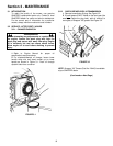
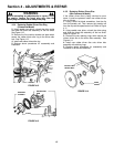
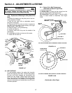
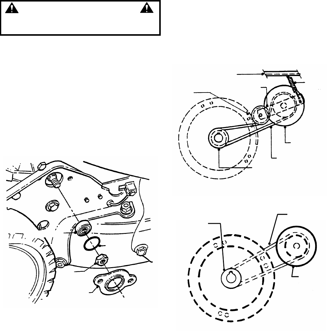
4.3.8. Replacement Of Bearing On Pulley End Of Hex
Shaft
To replace the bearing on the pulley end of the hex
shaft, proceed as follows:
1. Hold the hex shaft with an adjustable wrench
held next to the pulley.
2. Remove the 3/8” hex lock nut which is located at
the end of the hex shaft on the outside of the right
wheel bracket. See Figure 4.17.
3. Remove holder, O-ring and bearing.
4. Install new bearing.
5. Carefully install new O-ring over the outside of the
new bearing.
6. Install bearing holder and secure with screws.
7. Install 3/8” hex lock nut.
FIGURE 4.17
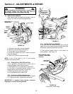
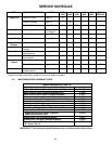
4.4. BELT SERVICE
On self-propelled mowers, the engine belt transmits
power from engine to drive disc. The drive disc powers
the poly-v belt which engages the transmission that
powers the rear wheels. Should these belts become
worn, they could cause slippage which would impair
mower performance. The condition of the engine belt
and poly-v belt should be checked after every 25 hours
of mower operation.
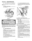
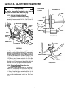
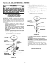
4.4.1. Engine Drive Belt Replacement
(Standard and Stretch Type Belts)
1. Empty the fuel tank.
2. Standard Belt: Unhook the idler spring from the
right rear wheel bracket. See Figures 4.18.
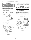
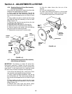
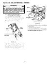
2.A. Stretch Belt: Proceed to Step 3. There is no idler
pulley on these models to disconnect. See Figure
4.18A.
FIGURE 4.18
TOP VIEW OF ENGINE WITH STRETCH TYPE BELT ROUTING
FIGURE 4.18A
(Continued on Next Page)
BALL BEARING
“O” RING
3/8”
LOCK
NUT
BALL
BEARING
HOLDER
RIGHT REAR WHEEL
BRACKET
SLOT IN
DECK
IDLER
ARM
IDLER
SPRING
DRIVE DISC
DRIVE BELT
ENGINE DRIVE PULLEY
TOP VIEW OF ENGINE WITH STANDARD TYPE BELT ROUTING
DRIVE DISC
DRIVE BELT
ENGINE DRIVE
PULLEY