


14
Section 4 - REPAIR & ADJUSTMENTS
WARNING
Before attempting any adjustments, maintenance,
service, or repairs, stop engine and auger, always
remove key from ignition switch, remove spark plug
wire and secure wire away from spark plug.
4.1 AUGER BELT ADJUSTMENT/REPLACEMENT
When operating machine release the auger clutch
control, auger should come to a complete stop in 5
seconds. If auger does not come to a complete stop in
the required time, check and adjust belt tension.
Inspect belt frequently for signs of excessive wear.
Observe drive belt for slippage due to wear when
operating machine. If slippage does occur adjust as
follows.
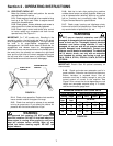
4.1.1. AUGER and DRIVE BELT ADJUSTMENT
(CABLE ADJUSTMENT)
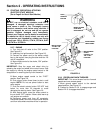
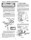
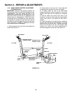
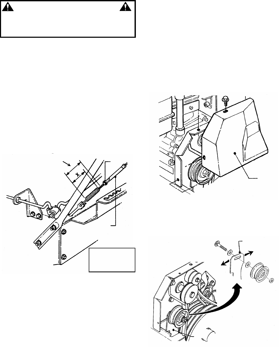
1. Measure control cable extension from a relaxed
position to full extended position. Move control lever
against handle. Measure from the top of spring (The
top is in relation to where spring connects into
connector). Proper extension should be 3/8” extension.
See Figure 4.1.
FIGURE 4.1
2. Adjust control cable by loosening jam nut at the
upper end of cable. Hold threaded end of cable and
then turn cable clockwise or counter clockwise until
correct extension is achieved. Retighten jam nut.
IMPORTANT: DO NOT rotate cable beyond the point to
where all of slack is out of cable. Cables have to have a
certain amount of slack: When control lever is in the
released position the cable slack allows: 1) Auger brake to
stop auger. 2) Wheel drive to disengage. If all of the
adjustment is utilized at the upper handle go to Section
4.1.2. for alternate adjustment.
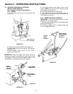
4.1.2. AUGER BELT ADJUSTMENT
(IDLER PULLEY ADJUSTMENT)
NOTE: Wheel drive belt idler pulley is not adjustable. If
upper cable adjustment performed in Section 4.1.1.
and correct cable extension can not be accomplished,
adjustment can be made at the idler pulley. All
adjustment made in Section 4.1.1. will have to be
reversed from the upper end of cable.
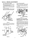
1. Loosen jam nut at the end of cable. Hold threaded
end of cable and then turn metal housing of cable
counter clockwise until threaded portion of cable is
extracted from metal housing. Reinstall 1/2” of the
threaded portion of cable back into metal housing.
Retighten jam nut.
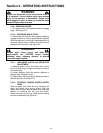
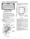
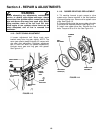
2. Remove belt cover. See Figure 4.2
FIGURE 4.2
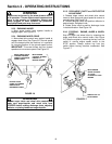
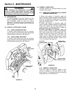
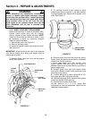
3. Loosen nut and bolt that secures the idler pulley.
Move idler toward belt for more tension or away from
belt for less tension. See Figure 4.3. Retighten bolt and
nut securely.
FIGURE 4.3
CONNECTOR
JAM
NUT
(WHEN ENGAGED)
X+3/8”
SPRING SHOULD
STRETCH 3/8”
WHEN HANDLE IS
DEPRESSED
REMOVE
BELT
COVER
IDLER ARM
IDLER PULLEY ASSEMBLY
SHOWN EXPLODED TO
SHOW DETAIL OF IDLER
ARM SLOT
LEFT
RIGHT
MOVE IDLER PULLEY TO
LEFT INCREASE OR TO
RIGHT DECREASE
TENSION ON BELT
IDLER
ARM