


12
Section 4 - REPAIR & ADJUSTMENTS
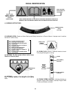
WARNING
DO NOT attempt any maintenance, adjustments or
service with engine and blade running. STOP engine
and blade. Disconnect spark plug wire and secure
away from spark plug. Engine and components are
HOT. Avoid serious burns, allow sufficient time for all
components to cool. Wear heavy leather gloves when
handling or working around cutting blades. Blades
are extremely sharp and can cause severe injury.
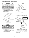
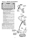
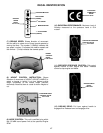
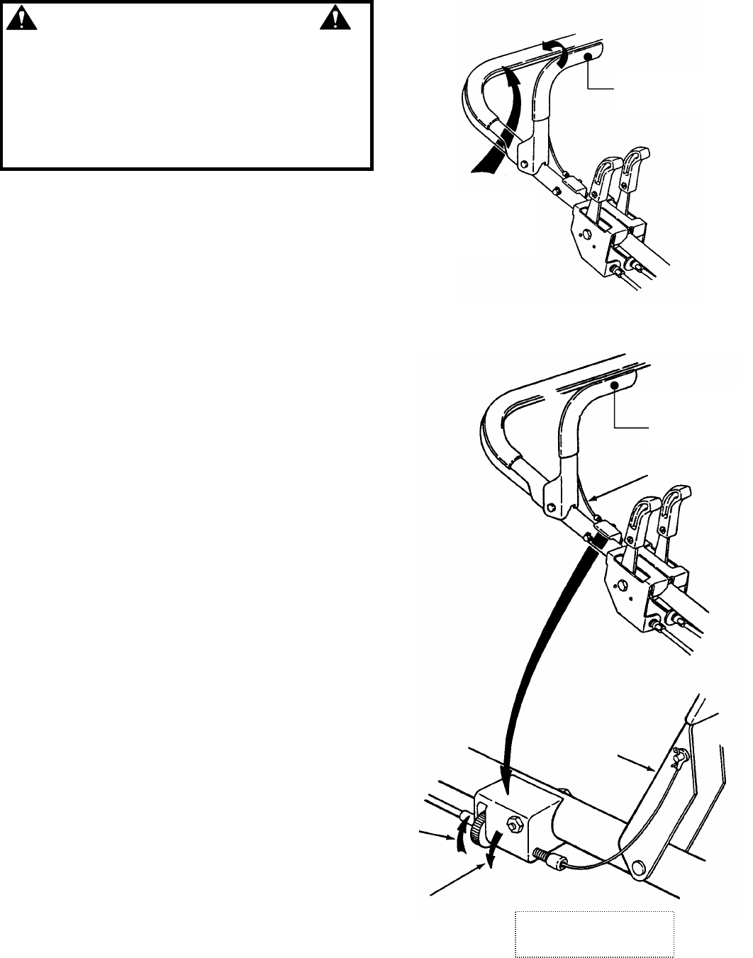
4.2 WHEEL DRIVE CONTROL ADJUSTMENT
(Engine To Transmission Deck Belt)
The wheel drive control requires periodic adjustment to
maintain proper engine to transmission drive belt
tension. The adjustment is located on the right handle
and requires no tools. See Figure 4.5.
IMPORTANT: DO NOT operate engine when
inspecting or adjusting the drive belt.
1. Visually check engine drive belt for cracking, fraying,
severed or belt strands exposed. Replace belt before
operating mower.
2. To check for proper drive belt tension. STOP
engine. Shift ground speed control to 1
st
and engage
the wheel drive control.
3. With the wheel drive control engaged, pull the
mower handles, moving the mower rearward. Observe
the rear wheels.
4. If the rear wheels slide on the surface (no rotation)
the belt is properly tensioned and the control does not
require adjustment.
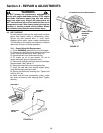
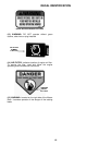
5. If the rear wheels rotate, increase belt tension by
rotating the thumb screw COUNTER-CLOCKWISE.
6. Turn thumb screw one turn at a time and recheck
tension (repeating steps 3-5).
7. When proper belt tension has been set, operate
machine and verify proper wheel drive control function.
IMPORTANT: DO NOT over-tighten wheel drive control. DO
NOT operate if control or drive does not function properly.
Contact your local SNAPPER Dealer for assistance.
IMPORTANT: If machine creeps forward after wheel
drive control is released the cable is too tight and must
be readjusted to eliminate all forward movement.
Machine must not have any forward movement when
wheel drive control is disengaged. If the wheel drive
control fails to return quickly to the “OFF” position when
released, check for a broken, binding, or kinked cable.
FIGURE 4.4
FIGURE 4.5
HOLD WHEEL
DRIVE AGAINST
HANDLE
HOLD BLADE
CONTROL
AGAINST
HANDLEBAR
RELEASE
WHEEL DRIVE
CONTROL
TURN ADJUSTING
WHEEL CLOCKWISE
TO INCREASE DRIVE
BELT TENSION
TURN ADJUSTING
WHEEL COUNTER-
CLOCKWISE TO
INCREASE DRIVE
BELT TENSION
CABLE
WHEEL
DRIVE
CONTROL
VIEW SHOWN FROM
OPERATOR’S POSITION