


2
Installation Instructions Hitch & Tube Group
Form No. 1726331-00
Rev. 12/2003
© 2003 Simplicity Manufacturing, Inc. All Rights Reserved
TP 200-4006-00-AT-SMA
MANUFACTURING, INC.
500 N Spring Street / PO Box 997
Port Washington, WI 53074-0997 USA
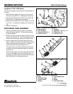
Figure 3. Landlord Hitch Installation
A. Hitch Bracket E. Drawbar
B. Hitch Support F. Capscrew, 1/2-13 x 1-1/4
C. Capscrew, 3/8-16 x 1 G. Flat washer, 1/2
D. Locknut, 3/8-16 H. Locknut, 1/2-13
D
C
H
F
G
B
A
E
G
C
D
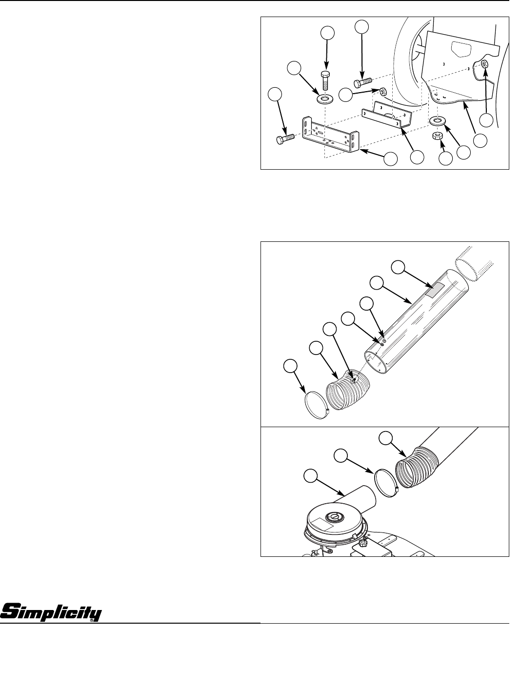
Figure 4. Discharge Tube Installation
A. Decal E. Truss Head Screw
B. Discharge Tube F. Hose
C. Locknut, Hose G. Clamp
D. Washer H. Turbo Discharge
G
H
F
A
B
C
D
E
F
G
Landlord / 1700 / 2700 Series
NOTE: Do not tighten hardware until all components are
installed.
1. Mount the hitch support (B, Figure 3) to the rear of
the tractor using 3/8-16 x 1 capscrews and locknuts.
2. Secure the hitch bracket (A) to the hitch support (B)
using 3/8-16 x 1 capscrews and locknuts.
3. Secure the hitch bracket (A) to the drawbar (E) using
a 1/2-13 x 1-1/4 capscrew, washers (G), and locknut
(H).
4. Tighten all hardware.
DISCHARGE TUBE ASSEMBLY
1. Connect the flexible hose (F, Figure 4) and clear
plastic discharge tube (B). The two should overlap
by approximately 2”.
2. Secure the tubes using truss head screws (E), wash-
ers (D), and locknuts (C). Insert the screws from the
inside out and poke them through the flexible hose.
3. Insert the upper end of the clear tube into the cart
sleeve. Slide the flex hose (F) over the turbo (H) and
secure with the large hose clamp (G). The hose
should overlap the turbo discharge by 2”-3”.
The clamp screw should be positioned to the inside
as shown to prevent accidental impact and removal
of the clamp.
Check that the upper end of the clear tube (B, Figure
4) is not contacting the top of the collector cover. If
necessary, cut off the clear tube flush with the sleeve
(See Wide Body Cart Operators Manual).