


11
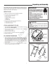
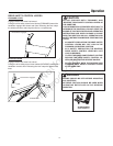
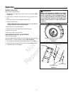
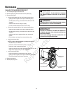
WHEEL LOCK PINS
Place wheels in tilling position.
1. Remove lock pin. Align hole in axle with hole in wheel hub. (SEE
FIGURE 2)
2. Insert lock pin through holes, fold lock pin ring to secure pin to
axle.
3. Firmly lock wheel and axle together before tilling.
4. Repeat for other wheel.
NOTE: Always have both wheel lock pins in or out. Do not
operate tiller with only one wheel locked.
To place wheels in free-wheel position.
1. Remove lock pin. Slide wheel inward toward machine.
2. Insert pin in axle only.
3. Wheel should turn freely on axle.
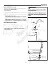
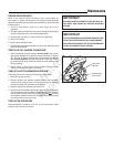
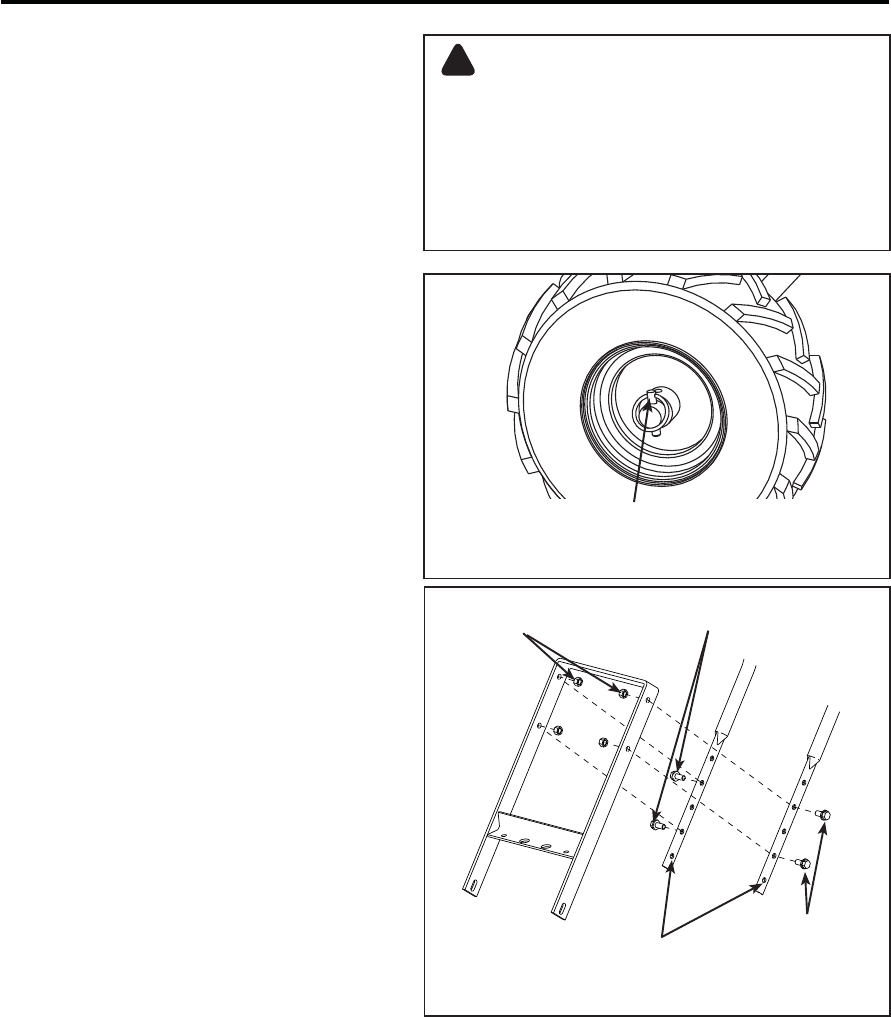
HANDLEBAR HEIGHT ADJUSTMENT
Adjust handlebar height.
The ideal height of the handlebar varies with operator height and the
depth of tilling. To adjust handlebar height: (SEE FIGURE 3)
1. Unscrew nuts and remove top and bottom bolts on each side.
2. Align handlebar to desired holes on the lower handlebar mount.
3. Install bolts and nuts. Retighten.
Wheel lock pin in free-wheel position.
(axle hole only)
NEVER START ENGINE OR OPERATE TILLER WITH
WHEELS IN FREE-WHEEL POSITION. THE FREE-
WHEEL POSITION IS FOR TRANSPORTING THE
TILLER LONG DISTANCES OVER LEVEL GROUND-
-DO NOT ATTEMPT TO MOVE THE TILLER UP OR
DOWN STEEP GRADES IN THE FREE-WHEEL
POSITION.
WARNING
!
height
adjustment holes
lock nuts
height
adjustment bolts
height
adjustment bolts
FIGURE 2
FIGURE 3
Operation
Not for
Reproduction