


3
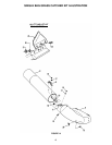
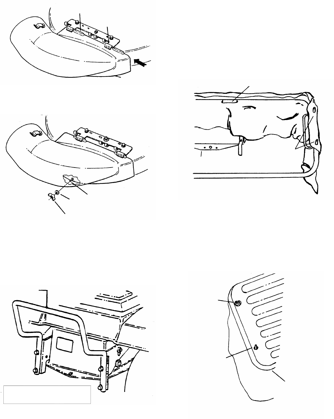
FIGURE 5B
FIGURE 5C
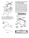
STEP 6: Adapter Kit Installation (Tractors only).
Install Adapter Kit #6-1334 per instructions supplied with
kit. See Figure 6.
FIGURE 6
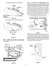
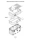
STEP 7: DUST SKIRT TO FRAME INSTALLATION
Punch out or tear out the center portion of the
reinforcement patches (There are two large ovals and
five small round patches) on dust skirt. Insert the legs of
the frame through the two larger holes in the skirt.
Position the five patches over the studs on the frame
(make sure square shield patch on skirt is installed on
muffler side). See Figure 7. Then push the frame down
over the bumpers. NOTE: Skirt should be on outside of
frame and should pass between frame and bumpers.
Insert pins in upper holes in bracket to lock frame in
place. Install clevis pins through holes and secure with
hair pins. Refer to exploded illustration on page 6.
FIGURE 7
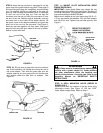
STEP 8: Install the grass catcher latch (item 13) on the
outside of frame using the #10-3/8” long cap screw (Item
14) on outside of frame and with the #10-32 lock nut
(item 15) on the inside. Tighten nuts and screws
securely but still allow the latch to rotate. Refer to
exploded illustration on page 6. Position the container
top over the studs of the frame and secure with the five
5/16” faceted washers. See Figure 8.
FIGURE 8
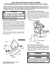
RETAINING
RIDGES
ENGAGEMENT
LUGS
TRACTOR MODEL SHOWN (DEFLECTOR REMOVED)
ADAPTER
POSITION ADAPTER
FORWARD OF
ENGAGEMENT LUGS
BOLT
WASHER
WING NUT
TRACTOR MODEL SHOWN (DEFLECTOR REMOVED)
BUMPER
KIT #6-1334 SHOWN INSTALLED
ON LT LAWN TRACTOR
LEGS OF FRAME ARE THROUGH LARGE OVAL SLOTS
POSITION
SKIRT OVER
STUDS
REAR OF RIDER
FACETED
WASHER
STUD
CONTAINER
TOP