


32
www.SnapperPro.com
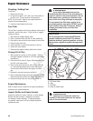
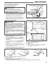
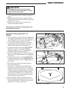
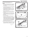
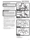
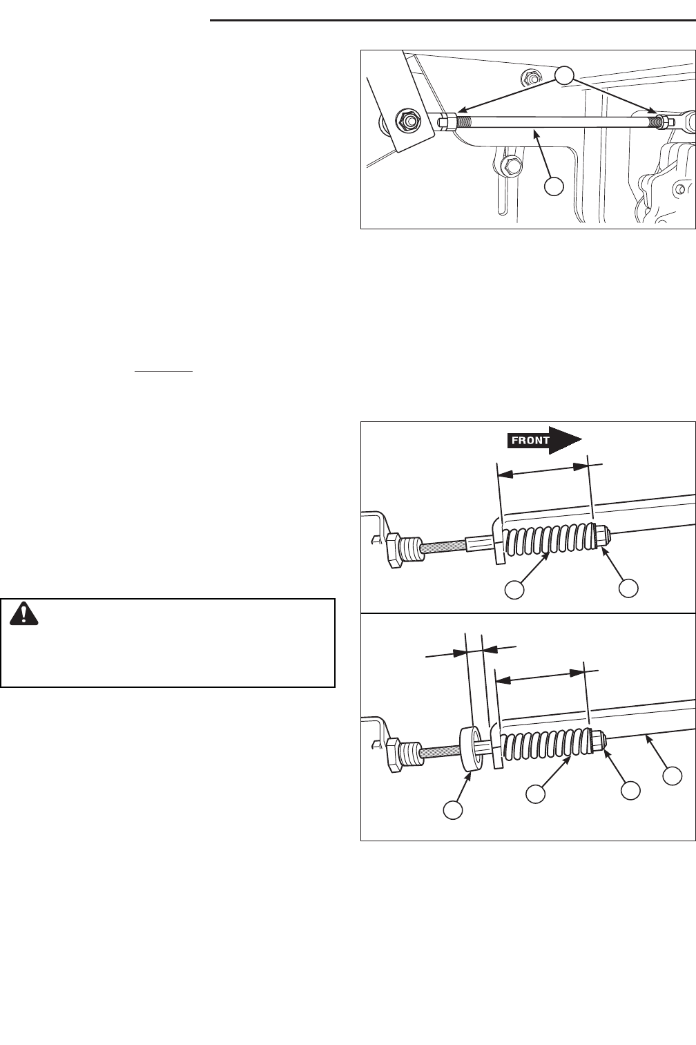
Figure 35. Parking Brake Adjustment
A. Brake Spring
B. Adjustment Nut
C. Set Collar
D. Parking Brake Bracket
Parking Brake Adjustment
1. Disengage the PTO, stop the engine, block the front
wheels, remove the ignition key, and engage the parking
brake.
2. Locate the brake spring (A, Figure 35).
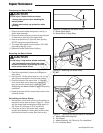
S/N: 2014161188 & Below
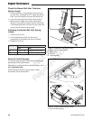
3. With the parking brake engaged, measure the
compressed spring length. The spring should be 2-3/8”
(6,0 cm) when compressed.
4. If the spring is not within this range, release the parking
brake and turn the adjustment nut (B) to compress or
release the spring.
5. Engage the parking brake and remeasure the spring.
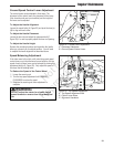
S/N: 2014161189 & Above
3. With the parking brake engaged, measure the
compressed spring length. The spring should be 2-3/4”
(7 cm) when compressed.
4. If the spring length does not equal the measurement, the
spring length will need to be adjusted.
5. Disengage the parking brake.
6. Loosen the set collar (C) and slide it away from the back
of the parking brake bracket (D).
2-3/8"
(6,0 cm)
2-3/4”
(7 cm)
1/8”
(0,3 cm)
A
B
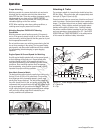
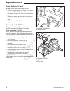
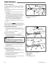
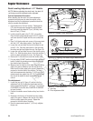
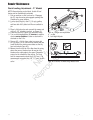
Neutral Adjustment
If the tractor “creeps” while the ground speed control levers
are locked in NEUTRAL, then it may be necessary to adjust
the linkage rod.
NOTE: Perform this adjustment on a hard, level surface such
as a concrete floor.
1. Disengage the PTO, engage the parking brake and turn
off the engine.
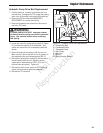
2. There are two nuts (B, Figure 34) on the linkage rod.
Loosen the nuts from the ball joints and turn the linkage
rod (A) to adjust. If the machine creeps forward, turn
the rod CLOCKWISE (while standing at the rear of
the machine, facing forward), if the machine creeps
backward, turn the rod COUNTERCLOCKWISE.
3. Lock the nuts (B) against the ball joints when neutral is
achieved.
NOTE: This adjustment should not be performed while the
machine is running. It may take several attempts to achieved
neutral, depending upon how much the machine creeps.
Regular Maintenance
CAUTION
Do not adjust the spring to be shorter than
2-5/16” (5,9 cm) when compressed. This may
damage the brake mechanism.
Figure 34. Neutral Return Adjustment
A. Adjustment Linkage Rod
B. 5/16” Nut
A
B
A
B
D
C
Not for
Reproduction