


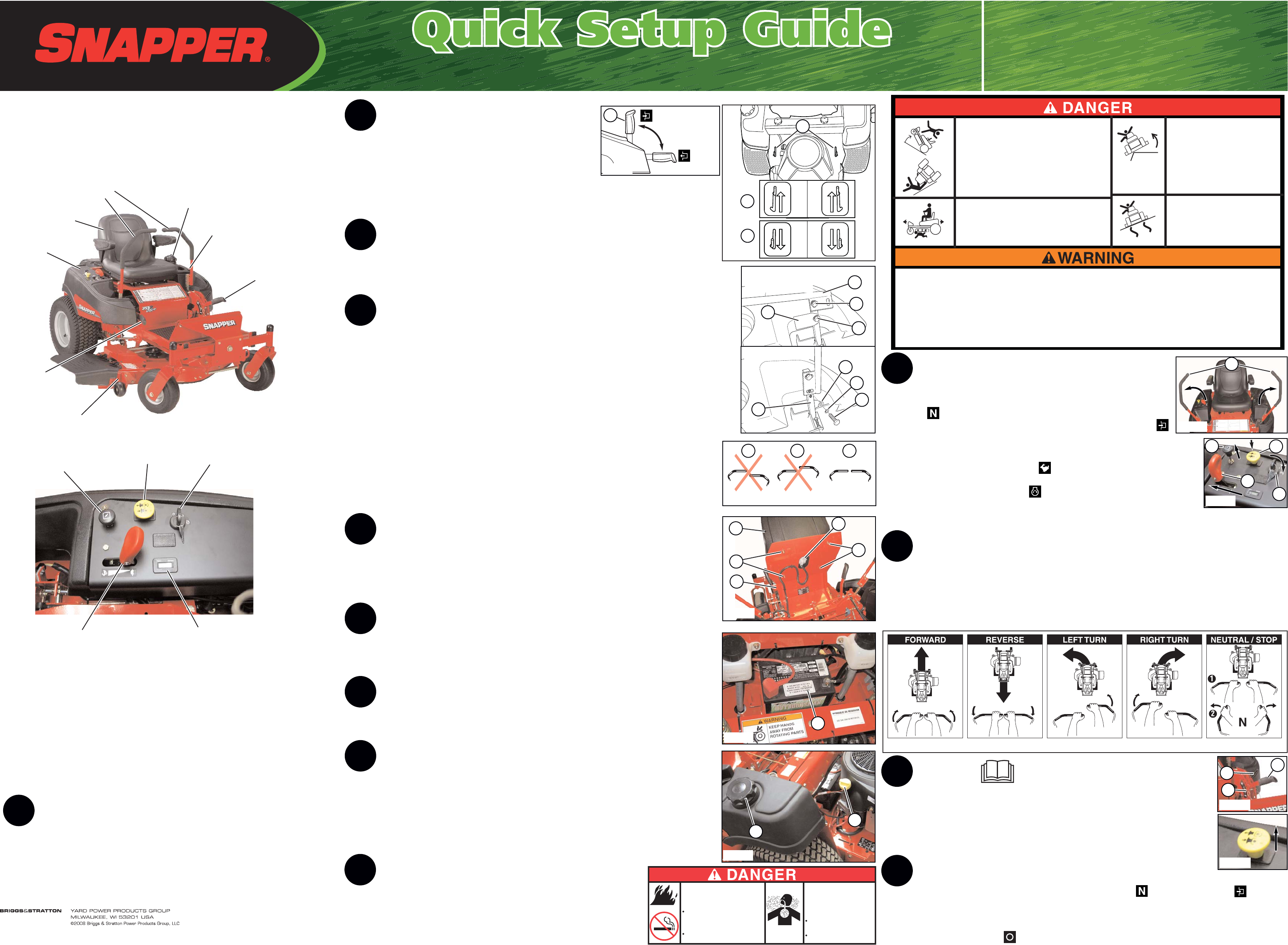
Start the Engine
• Sit in the seat.
• Pivot the ground speed / steering control levers (A, Figure 8) out to the
neutral ( ) position.
• Pull the parking brake lever (A, Figure 1) back and up to the engaged ( )
position.
• Make sure the PTO (blade engage) switch (A, Figure 9) is in the down
(DISENGAGED) position.
• Move the throttle control (B) to FAST ( ).
• Pull the choke control (C) up to CHOKE.
• Turn the ignition key (D) to START ( ).
• After the engine starts, release the ignition key, push the choke control down to
OFF, and reduce the throttle to half speed to allow the engine to warm up.
Note: For normal mowing set the throttle control to FAST.
Driving the Zero-Turn Riding Mower
Note: It is highly recommended that you read the Basic Driving Section of your operator’s manual before
attempting to drive the mower. The ground speed / steering control levers are responsive, and learning to
gain a smooth and efficient control of the zero-turn rider’s forward, reverse and turning movements will take
some practice. Practice driving the mower on a flat, level surface where there is plenty of room to maneuver.
Position the throttle to half speed and move the ground speed / steering control levers gently until you
become accustomed to how the zero-turn rider handles before attempting more complex maneuvers.
Mowing Read the Operator’s Manual before mowing.
• Pull the mower deck lift lever (A, Figure 11) all the way up until it latches in the
transport position. Position the cutting height selector pin (B) in the appropriate
hole to achieve the desired cutting height. Pull back on the mower deck lift lever
and the lock lever (C) simultaneously and lower the mower deck lift lever down
against the cutting height selector pin.
• Pull the PTO (blade engage) switch (Figure 12) up to engage.
Stopping the Rider, Blades, and Engine
• Return the ground speed / steering control levers to the neutral ( ) position and engage ( ) the
parking brake.
• Push the PTO (blade engage) switch down to disengage.
• Move the throttle control to the mid-throttle position.
• Turn the ignition key to OFF ( ). Remove the key.
Push the Unit off the Crate
• Disengage the Parking Brake (A, Figure 1) by pushing the
lever forward and down.
• Disengage the Transmission Release Levers (A, Figure 2), by
pulling them back and out towards the side of the machine (C).
• Roll the unit off of the crate.
• Engage the Parking Brake by pulling the parking brake lever up and back.
• Engage the Transmission Release Levers (B, Figure 2).
Read the Manuals
• Locate the operator’s manual in the manual packet. You should always read and follow the
instructions in the operator’s manual. Proper care, performance tips and safety information
are located in this important document.
Install the Ground Speed / Steering Control Levers
• Positioning the Ground Speed / Steering Control Levers
The ground speed / steering control levers (A, Figure 3) must be moved to the upright position
before attempting to operate the machine.
1. Remove the bottom mounting hardware (B). Discard the manilla tag (C).
2. Loosen the upper mounting hardware (D).
3. Position the ground speed / steering control levers in the upright position. See Figure 3.
4. Loosely install the 5/16-18 X 1” bolt (E), 5/16” lock washer (F), 5/16” flat washer (G) that was
removed in step 1, through the ground speed / steering control lever into the control lever base
(H) as shown in Figure 3.
5. Repeat process for other side of unit.
• Lever Alignment Adjustment: From the neutral position, pivot the ground speed / steering
control levers in towards the center of the machine. If one of the levers is tilted futher forward
(B, Figure 4) or back (A) then the other lever, pivot the levers foward or backwards to align
(C) with each other. Tighten the mounting bolts.
Install the Seat
• Install the seat (A, Figure 5) onto the seat plate (B) and fasten securely with the 5/16” nylock
flange nuts (C).
• Press the seat switch wire harness end onto the seat switch (D, Figure 5) until the latch of the
seat switch wire harness end snaps down over the lock on the seat switch.
Charge the Battery
• Check the date on the top or side of the battery (A, Figure 6). If the unit is being put into service
after the date indicated on the battery, charge the battery for one hour at 6-10 amps.
Check the Tire Pressure
• Adjust the air pressure of the rear tires to 15 PSI, and the front tires to 25 PSI.
Check the Engine Oil Level
Note: The engine is shipped with oil. However, the oil level should be checked before attempting to
start the engine. The unit should be parked on a flat, level surface to check the oil.
• Remove the oil fill cap (A, Figure 7). Wipe the dipstick, replace the cap, then remove and check
the oil level. The oil level should be between the ‘Full’ and ‘Add’ marks on the dipstick.
• If necessary, add premium 10W-30 oil to the engine. Recheck the oil level.
• Replace and secure the oil fill cap.
Add Fuel
• Remove the fuel cap (B, Figure 7).
• Add clean, fresh, unleaded fuel with a minimum of 87 octane
to the fuel tank.
• Replace the fuel cap, and wipe up any fuel that may have spilled.
Unit Features and Controls
Ground Speed /
Steering Control
Levers
Mower
Deck
Mower
Deck Lift
Lever
Seat
Parking
Brake Lever
(Disengaged
Position)
Throttle
Control
Ignition
Switch
Hour
Meter
PTO (Blade
Engage)
Switch
Choke
Control
Instrument
Control Panel
(See Below
for Individual
controls)
• Manual Packet
• Seat
• Ground Speed / Steering Control
Levers
• Set of Two Ignition Keys
• Hardware Bag (Located Inside of
Manual Packet) includes:
• 5/16” Nylock Flange Nut (4) for
installing seat.
• Unleaded Fuel (Minimum of 87 Octane)
• 6-10 Amp Battery Charger
• Tire Pressure Gauge
• 1/2” SAE Socket Wrench
7
6
5
4
3
2
10
Amputation hazard
To avoid injury to children, stop mower when
children are near. Do not mow in reverse.
Look behind when backing. Never carry
riders, especially children.
Read operator's manual(s).
Know location and function of all controls.
Keep safety devices (guards, shields & switches) in place
and working.
Remove objects that can be thrown by the blade.
Do NOT mow when children or others are around.
NEVER carry children, even with blades off.
Look down and behind - before and while backing.
Avoid sudden turns.
Go across slopes, NOT up and down.
If machine stops forward motion on a slope, stop the blades
and drive slowly off the slope.
Be sure blades and engine are stopped before placing hands
or feet near blades.
When leaving machine, shut off engine, remove key, and set
parking brake.
Do NOT operate this machine unless you are trained.
Operating on slopes can be hazardous.
Operating on steep slopes can cause sliding
and loss of steering, control and rollover.
See operator's manual.
Reduce speed and use extreme caution on slopes.
Avoid sudden turns or rapid speed changes.
Do NOT operate on slopes over 15°.
Operating on wet or slippery
slopes can cause sliding and
loss of steering and control.
Do NOT operate on any slopes
when wet or slippery.
Wheels dropping over edges,
ditches or embankments can
cause rollovers, which may
result in serious injury, death
or drowning.
Do NOT operate near drop-offs or
near water.
11
12
355ZB2654
8
Figure 8
Figure 5
Figure 3
Figure 6
Items Needed for Assembly
Items Included with Unit
We reserve the right to improve our products and make changes in specifications, designs, and standard
equipment without notice and without incurring obligation.
Form No. 5101471
TP 1021-7371-IR-HZ-N
Fuel
Gauge
Fuel
Cap
Figure 1
Figure 10
Figure 2
B
C
C
C
A
D
B
A
Figure 7
A
9
B
Figure 9
A
C
A
D
B
13
Figure 11
Figure 12
Unpack the Unit
• Remove the top, sides and ends of the crate. If available, a reciprocating saw is the
best tool for the job.
• Remove all packaging materials from the crate and the unit. Remove any banding
securing the unit to the crate.
• Remove the plastic wrapping that holds the discharge chute in the upright position.
1
A
A
Engaged
Disengaged
Figure 4
A B C
Fire hazard
Gasoline is flammable.
Yard debris is combustible.
Allow engine to cool for at
least 3 minutes before
refueling.
Keep unit cleaned of debris.
Carbon monoxide
hazard
The engine emits poisonous
carbon monozide gas.
Avoid inhaling exhaust
fumes.
Only operate outdoors.
A
C
B
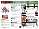
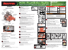
Zero-Turn Riding Mower Models 5900748 - 5900755
Questions?
Do not return to the store. We can help.
Call Customer Service Toll-Free
1-800-317-7833
Or visit our website www.snapper.com
Left Side Shown
C
B
D
A
H
G
F
E
Shipping Position
Upright Position