


21
Section 4 - ADJUSTMENTS & REPAIR
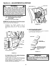
WARNING
DO NOT attempt any adjustments, maintenance, service
or repairs with the engine running. STOP engine. STOP
blade. Engage parking brake. Remove key. Remove spark
plug wire from spark plug and secure away from plug.
Engine and components are HOT. Avoid serious burns,
allow all parts to cool before working on machine. Fuel
Filler Cap and vent must be closed securely to prevent
fuel spillage. Once blade is disengaged it should come
to a stop in 3 seconds or less. If the blade continues to
rotate after 3 seconds the blade brake must be
adjusted. DO NOT continue to operate the machine if
the blade brake is not operating properly.
4.1 ENGINE ADJUSTMENTS & REPAIR
Refer to the engine owner’s manual for those
adjustments and/or repairs that can be made by the
owner.
4.2 MOWER DECK & COMPONENT ADJUSTMENTS
The following mower deck and component
adjustments and repairs can be made by the owner.
However, if there is difficulty in achieving these
adjustments and repairs, it is recommended that
these repairs be made by an authorized SNAPPER
dealer.
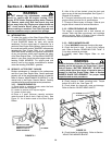
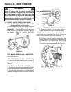
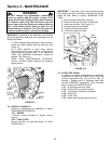
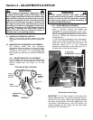
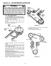
4.2.1. MOWER DRIVE BELT ADJUSTMENT
On 42” models, the mower drive belt DOES NOT
require adjustment. If the belt does not drive blade
properly, replace belt. See Figure 4.1 for belt
routing.
FIGURE 4.1
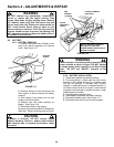
WARNING
DO NOT operate machine until blade brake is
adjusted and functioning properly. If blade stop time
cannot be achieved with the adjustment procedure
described above, take the machine immediately to
an authorized SNAPPER dealer.
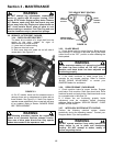
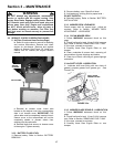
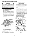
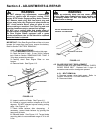
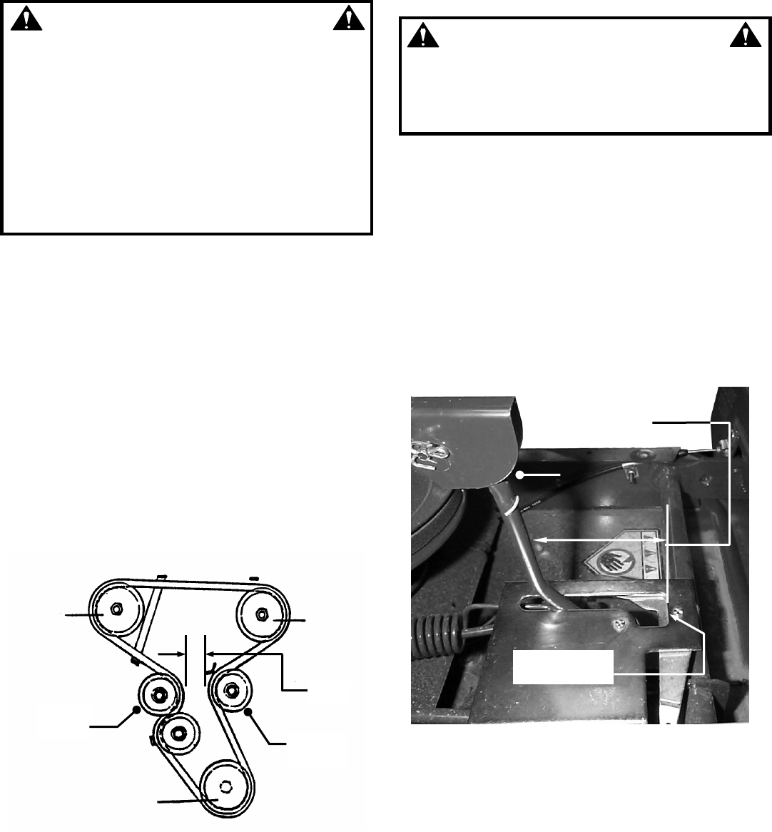
4.2.2. BLADE BRAKE ADJUSTMENT
The automatic Blade Brake should stop the blades
within 3 seconds anytime the blades are
disengaged by moving blade lever to the "OFF"
position or by releasing the Blade Pedals. Check
this by disengaging the Blade Lever as shown in
Figure 4.2. Perform the following measurement
and adjustment.
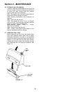
1. With the blade engagement lever disengaged,
measure the distance between the front of the
blade lever and the edge of the latch plate. The
dimension should be 3” to 3-1/4" clearance
between lever and edge of plate. See Figure 4.2. If
the dimension is incorrect go to step 2.
FIGURE 4.2
(Continued on Next Page)
IMPORTANT: On 42” deck models do not require belt
tension adjustment. But, if front frame assembly clamp is
loosened for any reason, recheck belt spacing between
idler pulley and fixed pulley. Place deck height lever in the
3rd position. With blade lever in the “ON” position, the
distance between the idler pulley and the fixed pulley
should be 2-1/8”. See Figure 4.1.
RIGHT
SPINDLE
PULLEY
LEFT
SPINDLE
PULLEY
TOP VIEW OF BELT ROUTING
ENGINE DRIVE
PULLEY
ASSEMBLY
3” to 3-1/4”
CLEARANCE
MEASURE FROM
THIS EDGE
BLADE
LEVER
DISENGAGED
2-1/8”
IDLER
PULLEY
FIXED
PULLEY