


17
Section 4 - ADJUSTMENTS & REPAIR
WARNING
DO NOT attempt any adjustments, maintenance, service
or repairs with the engine running. STOP engine. STOP
blade. Engage parking brake. Remove key. Remove
spark plug wire from spark plug and secure away from
plug. Engine and components are HOT. Avoid serious
burns, allow all parts to cool before working on machine.
Fuel Filler Cap and vent must be closed securely to
prevent fuel spillage.
4.1 ENGINE ADJUSTMENTS & REPAIR
Refer to the engine owner’s manual for those
adjustments and/or repairs that can be made by the
owner.
4.2 MOWER DECK & COMPONENT ADJUSTMENTS
The following mower deck and component
adjustments and repairs can be made by the owner.
However, if there is difficulty in achieving these
adjustments and repairs, it is recommended that
these repairs be made by an authorized SNAPPER
dealer.
WARNING
Once blade is disengaged it should come to a stop in 3
seconds or less. If the blade continues to rotate after 3
seconds the blade brake must be adjusted. DO NOT
continue to operate the machine if the blade brake is
not operating properly.
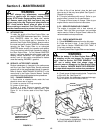
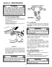
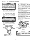
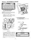
4.2.1. MOWER DRIVE BELT ADJUSTMENT
On 42” models, the mower drive belt DOES NOT
require adjustment. If the belt does not drive blade
properly, replace belt. See Figure 4.1 for belt
routing.
FIGURE 4.1
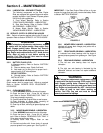
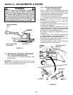
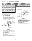
4.2.2. BLADE BRAKE ADJUSTMENT
The automatic Blade Brake should stop the blades
within 3 seconds anytime the blades are
disengaged by moving blade lever to the "OFF"
position or by releasing the Blade Pedals. When the
Blade Brake is properly adjusted there should be
1/16" to 1/8" clearance between the Blade
Engagement Lever and the back of the Latch Plate.
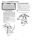
Check this by disengaging the Blade Lever and
depressing the Blade Pedals as shown in Figure
4.2. If clearance is greater than 1/4" perform the
following adjustment.
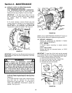
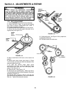
1. Remove mower drive belt cover.
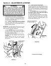
2. Remove retaining pin from eye bolt swivel. Lift
swivel out of deck rail. See Figure 4.2.
3. Turn eye bolt swivel CLOCKWISE to increase
brake tension and reduce clearance between Blade
Lever and Latch Plate.
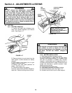
4. Check clearance. Depress Blade Pedals, with
Blade Lever disengaged. If clearance is greater
than 1/8", rotate eye bolt swivel CLOCKWISE an
additional turn and re-check clearance.
5. Once the 1/16" to 1/8" clearance has been
attained, reinstall swivel onto deck rail. Insert
retaining pin into eye bolt swivel.
6. Reinstall mower drive belt cover.
7. Verify that proper Blade Brake action has been
restored. If not, contact your SNAPPER Dealer for
inspection and repair.
FIGURE 4.2
WARNING
DO NOT operate machine until blade brake is adjusted
and functioning properly. If blade stop time cannot be
achieved with the adjustment procedure described
above, take the machine immediately to an authorized
SNAPPER dealer.
RIGHT
SPINDLE
PULLEY
LEFT
SPINDLE
PULLEY
TOP VIEW OF BELT ROUTING
ENGINE DRIVE
PULLEY
ASSEMBLY
ROTATE SWIVEL ON
EYE BOLT TO
ACHIEVE CORRECT
CLEARANCE
EYEBOLT
EYE BOLT
SWIVEL
RETAINING PIN