


19
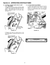
Section 4 - ADJUSTMENTS & REPAIR
WARNING
DO NOT attempt any adjustments, maintenance,
service or repairs with the engine running. STOP
engine. STOP blade. Engage parking brake. Remove
key. Remove spark plug wire from spark plug and
secure away from plug. Engine and components are
HOT. Avoid serious burns, allow all parts to cool
before working on machine. Fuel Filler Cap and vent
must be closed securely to prevent fuel spillage.
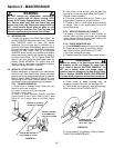
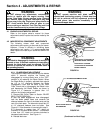
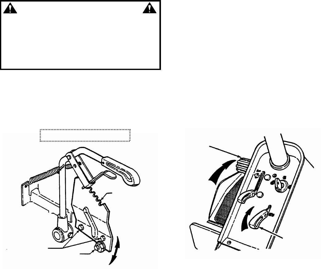
4.2.4. CUTTING HEIGHT ADJUSTMENT
The deck cutting height range may be adjusted.
1. Place the Rear Engine Rider on a smooth, level
surface.
2. Move deck lift lever to the lowest cutting position.
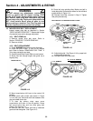
3. Loosen the two lift quadrant mounting bolts and
eccentric bolt. See Figure 4.5.
FIGURE 4.5
4. Rotate eccentric to raise or lower desired cutting
height range.
5. Tighten lift quadrant mounting bolts and
eccentric bolt.
NOTE: Lift quadrant in lowest position gives 1” to 3-1/2”
cutting height range. Lift quadrant in highest position
gives 1-1/2” to 4” cutting height range.
4.3 REAR ENGINE RIDER DRIVE COMPONENTS
Your Snapper rider is equipped with a patented
smooth start clutch. The clutch should operate
smoothly and provide ample traction. If problems are
experienced, contact your Snapper dealer for repair.
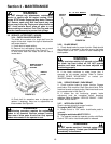
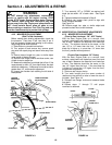
4.3.1 WHEEL BRAKE ADJUSTMENT
Test the wheel brake on a dry concrete surface.
When properly adjusted, the Rear Engine Rider will
stop within 5 feet from fastest speed. If stopping
distance is more than 5 feet, the wheel brake
should be adjusted as follows:
1. Follow WARNING statement found on this page.
Check fuel level in tank. Refer to Section
“REMOVING FUEL TANK”. If over 3/4 full, remove
tank.
2. If 3/4 or less, proceed to next step.
3. Carefully stand Rear Engine Rider on rear
bumper.
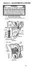
4. Depress clutch/brake pedal all the way down.
Move and hold the park brake lever in the “ON”
position and release the clutch/brake pedal to lock
the park brake. See Figure 4.6.
FIGURE 4.6
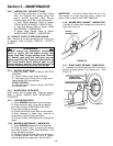
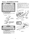
5. Measure the distance between end of
clutch/brake cable and bottom of housing.
Measurement should be no less than 1/2” and no
greater than 3/4”. See inset of Figure 4.7.
6. If measurement is less than 1/2” or greater than
3/4”, loosen the two jam-nuts. See Figure 4.8. Hold the
clutch/brake cable to the chain case bracket.
7. Adjust cable up or down using the jam-nuts to
obtain a distance of 1/2” to 3/4” between end of
clutch/brake cable (adjustment shown in inset of
Figure 4.7) and bottom of housing. See Figure 4.7.
(Continued on next page)
SHOWN WITH COVER REMOVED
RAISE OR
LOWER LIFT
QUADRANT AS
DESIRED
LOOSEN
MOUNTING
BOLTS
LOOSEN
ECCENTRIC BOLT
ROTATE
ECCENTRIC
PUSH CLUTCH/BRAKE
PEDAL ALL THE WAY
DOWN
MOVE PARK
BRAKE LEVER
TO “ON”