


2
4. With cell caps removed, connect battery charger to
battery terminals; RED to positive (+) and BLACK to
negative (-) terminal.
5. If time allows, slow charge at 1 amp for 10 hours, or
as an alternative, fast charge at not more than 2.5
amps for 4 hours to bring the battery to full charge.
NOTE: Slow charging is recommended and extends
battery life.
6. After charging, check level of electrolyte and add as
needed to bring level to 3/16” above cell plates.
7. Reinstall cell caps.
WARNING
Keep sparks and flames away from battery at all times!
Battery acid is corrosive. Rinse empty acid containers
with water and mutilate before discarding. If acid is
spilled on battery, bench, or clothing, etc., Flush with
clear water and neutralize with baking soda or ammonia
solution.
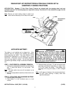
STEP 3: BATTERY INSTALLATION
1. Carefully place the charged battery, with terminals
toward front of tractor as shown on decal, in the
tractor battery compartment. See Figure 1.
2. Retrieve plastic bag from under the hood, on top of
gas tank. Remove nuts and bolts from plastic
hardware bag.
3. Connect positive (+) cable (red) from wiring harness
to the positive terminal (+) on battery using bolt and
nut provided in hardware bag..
4. Connect negative (-) cable (black) to negative
terminal (-) on battery using bolt and nut.
Note
: Shield the positive terminal with terminal cover
located on battery harness. This prevents metal
from touching the positive terminal which could
cause sparks.
5. Reinstall seat/pedestal assembly and tighten "Y"
knobs securely. DO NOT operate tractor without the
seat/pedestal assembly installed properly because it
serves as the battery hold down.
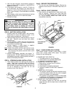
STEP 4: STEERING WHEEL INSTALLATION
1. Place steering wheel over steering shaft located on
tractor. Align hole in steering shaft with holes in
steering wheel and insert roll pin. Tap roll pin with
hammer gently through steering wheel and shaft until
roll pin is centered on the shaft. Do not use
excessive force! (See Figure 2)
FIGURE 2
Step 5: REDUCE TIRE PRESSURE
1. The tires are over-inflated for shipping. Reduce tire
pressure in front tires to 12 PSI and in rear tires to 12
PSI.
Step 6: INSTALL SEAT CUSHIONS
1. Seat cushions are positioned on rubber band under
seat for shipping. Remove from under seat and
install into seat support assembly as shown in Figure
3. Lip of cushion should lock under tab on
seat/pedestal assembly.
FIGURE 3
Step 7: CHECK INTERLOCK SYSTEM
The interlock system includes a seat switch, a clutch
switch and a mower blade (PTO) switch. The system
functions in the following way:
A. ENGINE MUST NOT START IF:
1. The blade control is in the ON position.
2. Clutch pedal is not completely depressed.
3. Operator is not seated on tractor.
B. ENGINE MUST START ONLY WHEN:
1. Blade control is shifted into OFF position.
2. Parking brake is set.
3. Clutch pedal is completely depressed.
4. Operator is seated in tractor seat in operator's
position.
C. ENGINE WILL STOP WHEN:
1. The operator vacates the seat with the blade control
in the ON position and/or with the clutch engaged
(when clutch pedal is not depressed).
2. The operator is not seated on tractor and the blade
is shifted into the ON position or engages the clutch
(clutch pedal is not depressed or is released).
D. ENGINE WILL CONTINUE RUNNING IF:
1. The operator vacates the seat with the parking
brake set and with the blade control shifted in the
OFF position.
SEAT
SEAT SUPPORT
BRACKET
CUSHION
SEAT/PEDESTAL
ASSEMBLY
“Y” KNOB