


ASSEMBLY
IMPORTANT: Read entire owner’s manual before you
attempt to assemble or operate your new pressure washer.
Remove Pressure Washer from
Carton
• Remove parts bag included with pressure washer.
• Slice two corners at end of carton from top to bottom
so panel can be folded down flat, then remove all packing
material.
• Remove pressure washer from carton.
Carton Contents
Check all contents.
• Main unit
• Engine Oil
• Safety Goggles
• High Pressure Hose
• Spray Gun
• Nozzle Extension
• Parts Bag (which includes the following):
• Owner’s Manual
• Engine Manual
• Owner’s Registration Card
• Maintenance Kit
• Handle Fastening Hardware Kit (which includes):
• Carriage Bolts (2)
• Plastic Knobs (2)
• “L” Hooks (2)
• Lock Nuts (2)
PREPARING PRESSURE
WASHER FOR USE
If you have any problems with the assembly of your
pressure washer or if parts are missing or damaged, call the
pressure washer helpline at 1-800-317-7833. If calling for
assistance, please have model, revision, and serial number
from data tag available.
To prepare your pressure washer for operation, you
will need to perform these tasks:
1. Fill out and send in registration card.
2. Add oil to engine crankcase.
3. Add fuel to fuel tank.
4. Connect high pressure hose to spray gun and pump.
5. Connect water supply to pump.
6. Attach nozzle extension to spray gun.
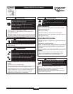
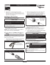
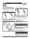
Attach Handle
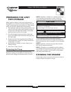
1. Place handle assembly onto handle supports connected
to main unit. Make sure holes in handle align with
holes on handle supports (Figure 1).
NOTE: It may be necessary to move the handle supports
from side to side in order to align the handle so it will slide
over the handle supports.
2. Insert carriage bolts through holes from outside of
unit and attach a plastic knob from inside of unit
(Figure 2).Tighten by hand.
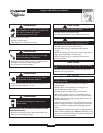
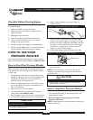
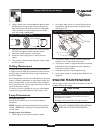
3. Insert one “L” hook through hole just under billboard
on left side of handle (viewing from rear of unit). Hold
hook in place with pliers and attach locknut with a
7/16” wrench (Figure 3).
6
Snapper 2300 PSI Pressure Washer
Hose Hook
Spray Gun
Hook
Figure 3 — Attach “L” Hooks to Handle
Align Holes
Handle
Handle
Supports
Figure 1 — Attach Handle to Base
Figure 2 — Secure Handle