


26
Adjustments & Service
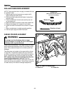
DRIVE BELT ADJUSTMENT (Continued)
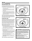
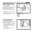
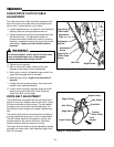
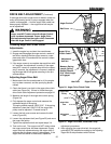
Adjusting Auger Belt Guide
1. With the auger control still fully depressed, adjust the
auger belt guide(s) so that there is a 1/64” gap (1/32”
Maximum) between the guide and the belt (Figures
26), making certain the guide is NOT putting pres-
sure on the belt.
2. Making certain the auger belt guide does NOT move
while doing so, tighten the auger belt guide screw
(Figures 26) to secure the guide.
3. Check the adjustment on the auger belt guide(s)
(Figures 26) to make certain that the gap between
the belt and the belt guide is correct.
4. Disengage the auger control by removing the card-
board tube (or other means used to temporarily
secure the control.)
5. Test the unit by following the steps under the
“Checking Auger Belt & Belt Guide Adjustments”
above.
WARNING
Failure to properly adjust the Auger Belt Guide(s)
may cause auger to rotate when Auger Control
has not been depressed.
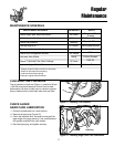
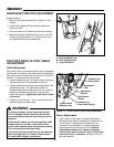
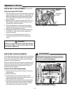
Figure 27. Traction Drive Pulley
(Lower Cover Removed For Clarity)
Traction Drive Belt & Pulley
DRIVE BELT REPLACEMENT
The snowthrower has two drive belts, one for the traction
drive—which transmits engine power to the wheels, and
a second for the auger drive—which transmits engine
power to the auger mechanism.
Each of these drive belts are of special construction and
should be replaced only with genuine replacement belts
which match the original equipment belts. These are
available from your dealer.
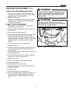
Traction Drive Belt Replacement
1. Disconnect spark plug wire and fasten it away from
the spark plug.
2. Remove belt cover.
3. Pull the traction drive belt idler pulley arm (See
Figure 22) away from the belt to relieve tension, and
slide the belt off the engine pulley.
4. Slip the belt off from around the traction pulley (See
Figure 27) and pull the belt out of the unit between
the auger pulley and the traction pulley (the lower
cover need not be removed for this step).
WARNING
Snowthrower must move only when the traction
Drive Control is depressed, and must stop when
the lever is released (disengaged).
Figure 26. Auger Belt Guide Adjustment
Belt Guide
& Gap
Belt Guide
Screws