


Initial
Installation
4
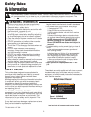
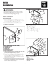
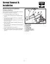
Before beginning any service work turn off the
PTO, set the parking brake, turn off the ignition,
and disconnect the spark plug wire(s).
WARNING
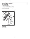
Figure 1. Install Spacer (left side shown)
A. Speed Nut, 5/16-18
B. Threaded Side
C. Square Hole
D. Shoulder Bolt, 5/16-18
E. Rear Frame Support
B
C
D
A
A
E
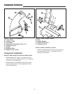
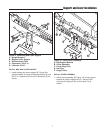
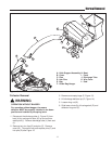
Figure 3. Hitch Installation
A. Hitch
B. Shoulder Bolt
C. Pin
D. Hole in Draw Bar
E. Hair Pin
A
B
D
E
C
Initial Installation
HITCH INSTALLATION
1. Slide the 5/16-18 speed nut (A, Figure 1) onto rear
frame support (E) through square hole (C) so that the
threaded side (B) is on the inside of tractor.
2. Secure the 5/16-18 shoulder bolt (D) as shown.
3. Repeat on the other side.
B
C
D
A
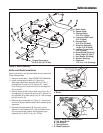
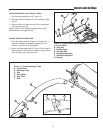
Figure 2. Frame Plate Reinforcement Installation
A. Frame Reinforcement
B. Rear Frame Support
C. Frame Support Hole
D. Capscrew, 5/16-18 x 1-1/4 (new)
E. Locknut, 5/16-18 (existing)
F. Capscrew, 5/16-18 (existing)
E
4. Remove existing nuts and capscrews from both sides
and rear frame support holes (C, Figure 2)
5. Secure frame reinforcement (A) to the inside of the
rear frame support (B) using new 5/16-18 x 1-1/4
capscrews (D) and existing 5/16-18 capscrews and
locknuts (E & F) as shown.
6. Slide the hitch (A, Figure 3) on right side and left side
shoulder bolt (B) while sliding pin (C) into hole (D) as
shown. Secure with hair pin (E).
D
F
C