


Troubleshooting, Adjustment & Service
23
00
NEUTRAL ADJUSTMENT
If the tractor “creeps” while the ground speed control
levers are locked in NEUTRAL, than it may be neces-
sary to adjust the linkage rod.
NOTE: Perform this adjustment on a hard, level surface
such as a concrete floor.
1. Disengage the PTO, engage the parking brake and
turn off the engine.
2. There are three (3) nuts on the linkage rod. The first
two are to be used together to turn the rod and the
third (towards the front of the machine) is used to
lock the rod in place. Loosen the jam nut that locks
against the clevis (B, Figure 19) and turn the linkage
rod (A) to adjust. If the machine creeps forward, turn
the rod CLOCKWISE (while standing at the rear of
the machine, facing forward), if the machine creeps
backward, turn the rod COUNTER-CLOCKWISE.
3. Lock the jam nut (B) against the clevis when neutral
is achieved.
NOTE: This adjustment should not be performed while
the machine is running. It may take several attempts to
achieved neutral, depending upon how much the
machine creeps.
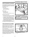
NEUTRAL POSITION & SPRING
RETURN ADJUSTMENT
Neutral Position Adjustment
If the machine “creeps” after the ground speed control
handles are brought into the operating position without
moving them forwards or backwards, it may be neces-
sary to adjust the neutral return arm position.
1. Lock the ground speed control levers in the neutral
position.
2. Loosen the hardware fastening the arm to the pivot
plate (D, Figure 20).
3. Slide the arm either forward or back until the bearing
on the control arm settles into the corner of the neu-
tral return arm.
4. Tighten the hardware when the neutral return arm is
in the proper position.
Neutral Return Adjustment
This adjustment will tailor the “feel” of the control levers
to the operator.
Each of the springs (A, Figure 20) has three adjustment
holes (B). The closer the spring is located to the neutral
return arm’s pivot (D), the less spring force will be felt by
the operator while driving and will return to neutral slow-
er.
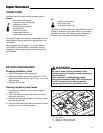
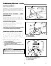
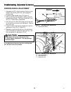
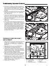
Figure 19. Neutral Adjustment
A. Adjustment Linkage Rod
B. Nuts
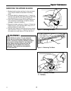
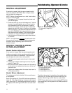
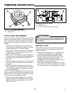
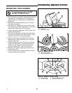
Figure 20. Neutral Spring Return Adjustment
A. Neutral Return Spring
B. Adjustment Holes
C. Neutral Return Arm
D. Neutral Return Arm Pivot
A
C
D
B
A
B
The farther the spring is located from the neutral return
arm’s pivot (D), the more spring force will be felt by the
operator while driving and will return to neutral faster.
NOTE: These adjustments must be made to BOTH sides
at the same time, and be placed in the SAME position to
one another.