14
SECTION 2 – OPERATING INSTRUCTIONS
2.2 CONTROLS – FUNCTION AND OPERATION
(Continued from previous page)
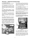
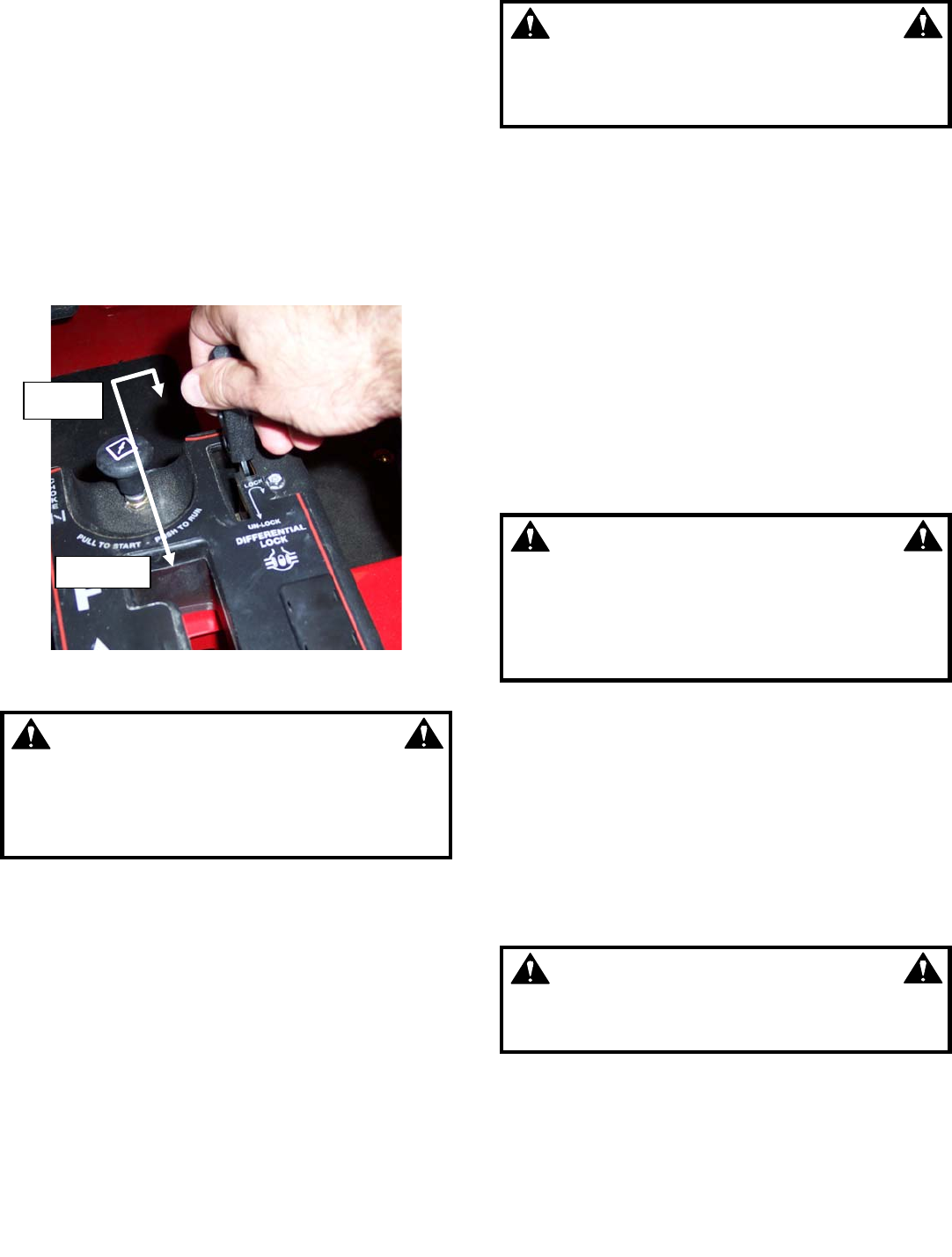
2.2.4. Differential Lock. The differential lock
increases traction by causing both rear wheels to pull
evenly. Move the lever towards the front of the slot and
latch to “Lock” the differential. (See Figure 2.4a.)
Unlatch the lever and move to the back of the slot to
“Unlock” the differential. Do not attempt to lock the
differential until all wheel rotation has stopped. Do Not
operate the machine in excess of 10 mph or attempt to
turn the machine with the differential locked. Always
unlock the differential when increased traction is no
longer needed.
FIGURE 2.4a
WARNING
DO NOT engage the differential lock with the
machine in motion or the rear wheels rotating.
Operate the machine with the differential locked
only at slow speeds, in a straight line and only
when increased traction is needed.
2.2.5. Accelerator Pedal. The accelerator pedal
controls the engine speed and the ground speed of the
machine. Depressing the pedal will increase engine
speed and cause the clutch to engage. The machine
will move in the direction selected with the shift lever.
The accelerator is also used to raise the engine speed,
with transmission in neutral, when warming a cold
engine. Always apply pressure to the accelerator
slowly and with caution. Do Not accelerate suddenly
and avoid sudden changes in speed. Release
accelerator before applying brake. Reduce speed
before turning. Refer to page 9 “Brake Pedal &
Accelerator Pedal”.
WARNING
DO NOT operate machine if accelerator pedal
movement is sticky or sluggish. Engine must
immediately return to idle speed when pedal is
released.
2.2.6. Choke. The choke control is used to help start
a cold engine. Pull choke knob up to apply (‘turn on’)
choke. Push knob down to open (‘turn off’) choke. Do
not operate the engine with the choke on. (NOTE: After
starting a cold engine, the choke may be partially
applied to assist running during the warm up period.)
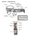
Refer to page 9 “Control Console”.
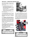
2.2.7. Seat Belt. A lap-style seat belt is provided for
the comfort and safety of the operator and one
passenger. Safe operation of the machine limits the
number of occupants to two. Both must be seated in the
seats provided with the seat belts buckled securely and
adjusted to a snug fit. To buckle the seat belt, insert
the latch plate fully into the latch. Check to make sure
that the belt is securely latched. Always adjust the seat
belt to a snug fit.
WARNING
DO NOT operate machine until operator and one
passenger are properly seated, with seat belts
securely latched and adjusted to a snug fit. Lap
style seat belts may not provide adequate
protection for small children. Carrying infants or
toddlers is not recommended.
2.2.8. 12 Volt DC Accessory Plug. The 12-volt
accessory plug, located behind the parking brake knob
on the control console, accepts cigarette lighter type
power adapters and can be used to power small
electronic devices. The ignition must be set to the
“RUN” position for the accessory plug to function.
NOTE: Operating a 12-volt accessory, especially with
the engine at idle, may cause battery to discharge.
NOTE: When not using accessory plug, be sure to
replace rubber cover. Entrance of water into plug can
cause short circuit.
WARNING
DO NOT exceed rated capacity of the 12 Volt
accessory plug. Replace fuses using same type
and rating only.
LOCK
UNLOCK
15


