


2
Installation Instructions
Idler Arm Replacement Kit
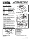
Figure 5. Correct Positioning Of The Spring Anchor
A. 5/16-18 Nylock Flange Nut
B. New Spring Anchor
C. Idler Spring
D. 5/16-18 x 1-1/4” Flange Bolt
B
A
7. Remove the mower belt. Remove the belt tension
release lever (A, Figure 2) from the guard notch to
release the tension on the spring.
8. On the center spindle, remove the 5/16-18 x 1-1/2”
bolt (A, Figure 4), spacer (B), and 5/16-18 hex nylock
flange nut (C) that secures the spring anchor (D) to
the spindle. Disconnect the idler spring that connects
to the idler arm and the spring anchor. Retain the
idler spring, and the nut. Discard the bolt, the spacer,
and the spring anchor.
9. Remove the spindle flange bolt (E) that secures the
spindle to the mower deck and reinstall the spindle
flange bolt in the hole that the 5/16-18 x 1-1/2” bolt
was removed from. Torque the spindle flange bolt to
14-18 ft. lbs (19-24 Nm.).
10. To remove the existing idler arm assembly: Loosen
the two 3/8-16 hex nylock flange nuts (H, Figure 6)
that secure the idler tension mount arm (G).
Remove the idler tension mount arm, the .39 x .75 x
.38 spacer (J), the 3/8 SAE washer (B), the idler
pulleys (F), the .39 x 1.00 x .88 spacer (I), the .39 x
.625 x 1.15 spacer (E), and the idler arm assembly
(D). Discard only the idler tension mount arm and the
idler arm.
11. Install the new idler arm (D, Figure 7) and the new
idler tension mount arm (G) exactly as shown in
Figure 7. Tighten the 3/8-16 flange nut (H) and the
3/8-16 x 3-1/2” bolt (A) first and then tighten the 3/8-
16 flange nut (H) and the 3/8-16 x 2-3/4” bolt (C).
The 3/8-16 x 2-3/4 bolt will position itself in the slot
on the idler tension mount arm.
12. Connect the idler spring (C, Figure 5) to the idler arm
and the new spring anchor (B). Install the new spring
anchor in the hole that you removed the spindle
flange bolt from in Step 9 with the new 5/16-18 x 1-
1/4 flange bolt (D) and 5/16-18 hex nylock flange nut
(A) and tighten.
13. Pull the lever (A, Figure 2) towards the rear of the
machine. Secure the lever in the guard notch (B).
14. Pivot the front wheels out of the way and slide the
mower under the unit.
15. Install the leveling links and hair pins (I, J, C & D,
Figure 3)
16. Lift the rear of the mower and install the rear lift rods
(K & L) and secure with the rear rod locks (E & F).
17. Install the roller bar connecting rod and hair pin (M).
18. Lift to front of the deck using a 2 x 4 as a lever, pull
the handle (G) to align the front hanger rod ends (H)
with the slots and secure with the front rod locks (A
& B).
19. Install the belt as shown in Figure 1.
20. Reapply tension to the mower deck belt by removing
the belt tension lever (A, Figure 1) from the guard
notch. Make sure the belt is seated properly in all
pulleys.
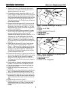
Figure 4. Incorrect Positioning Of The Spring
Anchor
A. 5/16-18 x 1-1/2” Bolt
B. Spacer
C. 5/16-18 Hex Nylock Flange Nut
D. Spring Anchor
E. Spindle Flange Bolt
F. Idler Spring
C
B
E
D
A
F
C
D